H3DS-F
H3DS-F
19
I/O Function
Inputs Flicker-ON
start operation begins when inputs are turned ON.
Outputs Control output
Outputs are turned ON/OFF according to the time set by the ON-and OFF-time setting dial.
Basic Operation
Setting
of Selector
The
selectors can be turned clockwise and counterclockwise to se
-
lect
the desired time scale, or operating mode.
Each
selector has a snap mechanism that secures the selector at a
given
position.
Set the selector at a position at which it is secured.
Do
not set it midway between two securing positions or a malfunc
-
tion
could result from improper setting.
Settings for ON/OFF Start
If voltage is applied to terminal B1, or if terminals A1 and B1 are
shorted,
the operating mode is switched to flicker-ON start mode. If
these
terminals are disconnected, the mode
switches to flicker-OFF
start mode. The operating mode will not change if the state of the
applied
voltage changes during timer operation.
Selection of T
ime Scale
The
time scale is selected by turning
the ON-time scale selector and
OFF-time scale selector
. The time scales will appear in the following
order
in each time
scale display window on the left of the selector:
0.1
s, 1 h, 0.1 h, 1 m, 1 s, 0.1 h, 0.1 m, 1 s.
Note: The time scales “1 s” and “0.1 h” appear twice. Both
instances
indicate exactly the same time scale.
ON-time scale
display window
and selector
OFF-time scale display
window and selector
Time
Setting
Use the ON/OFF-time setting dials to set the ON/OFF time.
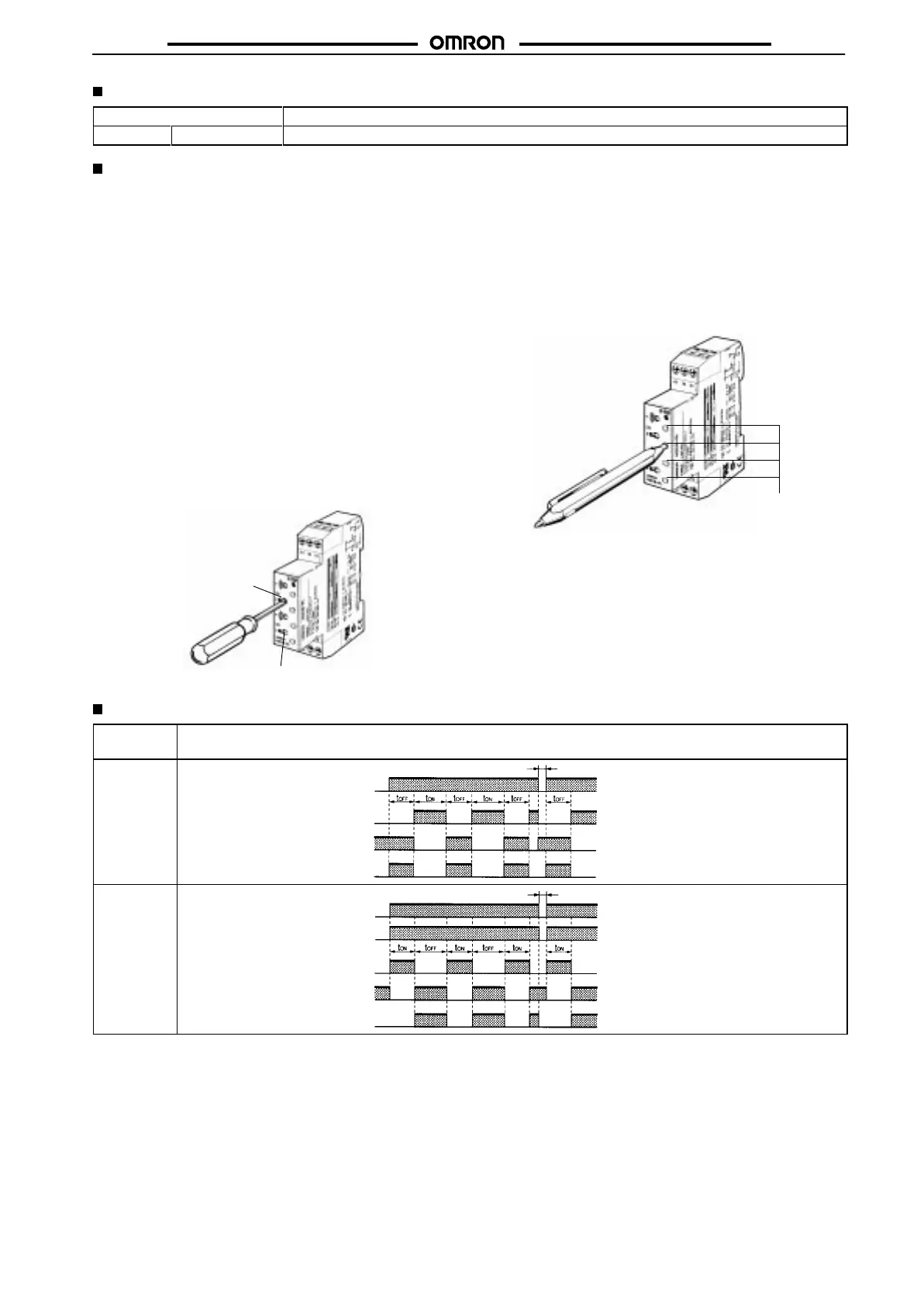
Locking/Unlocking of Selectors and Time Setting Dial
The ON/OFF-time setting dials and time scale selectors can be
locked
using the Y92S-38 Lock Key
, a special pen type tool that
is
sold
separately
. T
o lock the dials or selectors, insert the Lock Key in
the keyhole to
the
lower right of the dial or selector and turn it clock
-
wise until the dial or selector is completely covered with the red
cover.
T
o unlock, turn the Lock Key in the opposite direction.
Key hole
Timing Charts
Operating
mode
Timing
chart
Flicker-OFF
start
(See note 1.)
t
ON
: ON set time
t
OFF
: OFF set time
ON
OFF
ON
OFF
ON
OFF
Output relay: NO
15 and 18
(ON indicator)
Output relay: NC
15 and 16
OFF indicator
ON
OFF
0.1 s min.
Power (A
1
and A
2
)
Flicker-ON
start
(See
note 1.)
t
ON
: ON set time
t
OFF
: OFF set time
0.1 s min.
ON
OFF
ON
OFF
ON
OFF
ON
OFF
Power (A
1
and A
2
)
Output relay: NO
15 and 18
(ON indicator)
Output relay: NC
15 and 16
OFF indicator
ON
OFF
Signal (B
1
and A
2
)
Note: 1. If
voltage is applied to terminal B1, or if terminals A1 and B1 are shorted, the
operating mode is switched to flicker-ON start mode. If
these
terminals are disconnected, the mode switches to flicker-OFF start mode.
2.
The reset time requires a minimum of 0.1 s.
3. When
power is supplied in flicker-ON start mode, the OFF
indicator lights momentarily
. This, however
, has no ef
fect on the perfor
-
mance
of the T
imer.

 Loading...