H5S
10
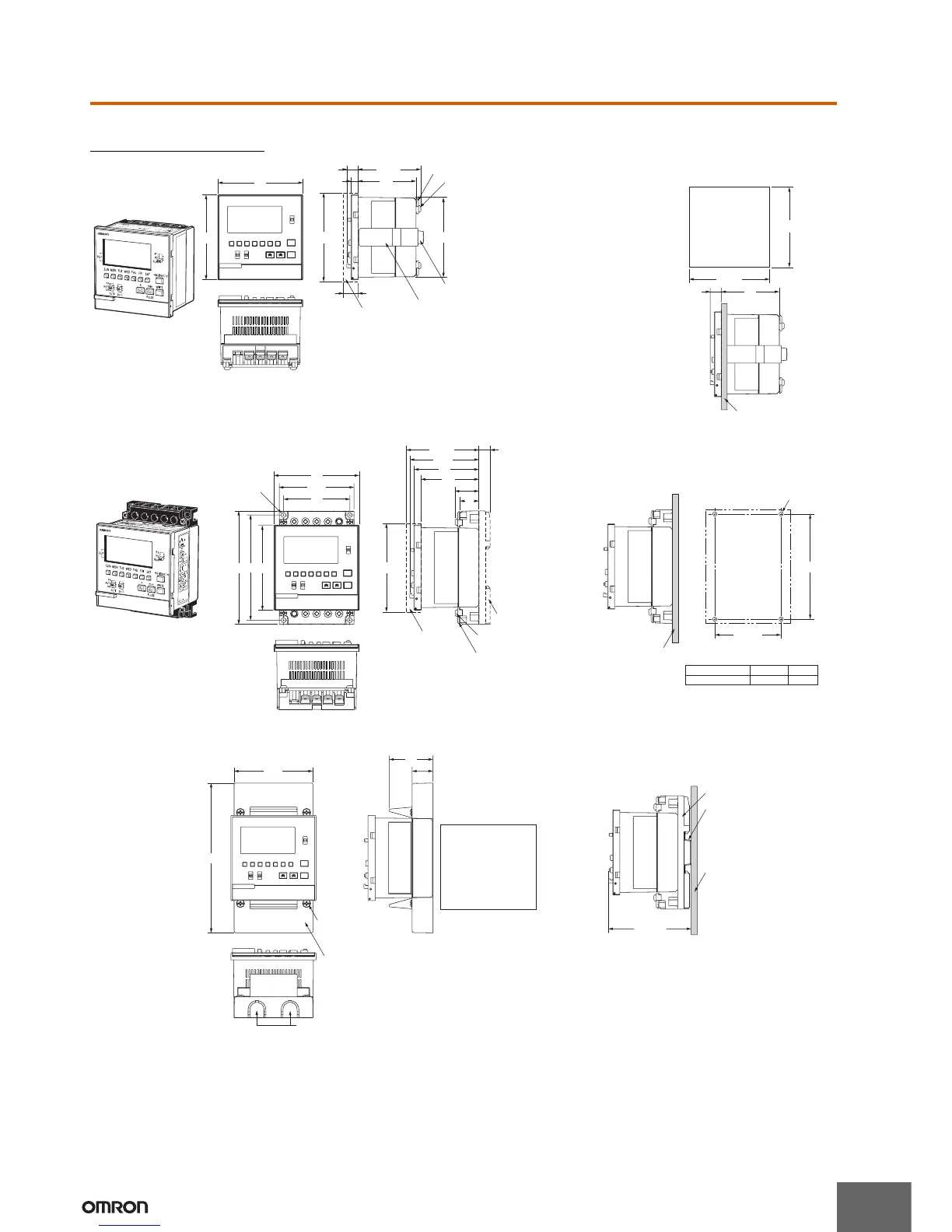
Dimensions
Note: All units are in millimeters unless otherwise indicated.
Digital Time Switch
Mounting bracket (included)
Four M3 x 8 screws (included) for mounting
the terminal covers
Two terminal covers (included)
Two M4 x 12 screws (included)
for the mounting bracket
Protective Cover
Y92A-72C (Order separately)
9.5
(53.2)
49
6
(75 × 75)
(12.5)
67.6 × 67.6
72
72
68
+
0.8
0
68
+
0.8
0
9.5
49
Mounting panel
H5S
TIME SWITCH
Flush Mounting Model
H5S-@A@/-@B@
Note: 1. The terminal screws are M3.5.
2. This illustration shows a 2-circuit model. The 4-circuit model
has the same dimensions.
Panel Cutout
Note: Panel thickness: 1 to 5 mm
Protective Cover
Y92A-72C (Order separately)
Y92F-90 DIN Track
Mounting Base
(Order separately)
Four M3 x 8 screws (included)
for mounting terminal covers
Two terminal covers (included)
(9.5)
55
49
(20.2)
16
(75 × 75)
(61.5)
58.5
Mounting holes
for four M4 screws
63.2
72
56
96 89 72
Mounting panel
89±
0.2
56±
0.15
4-dia. *
Panel thickness t
Hole diameter
0.8 to 1.2
3.6
1.6 to 4
3.7
*Diameter of pilot holes for
included M4 tapping screws (guideline)
17.7
37
Four M3 x 8 screws for
mounting the Y92A-72H
Large Terminal Cover
(included with the Y92A-72H)
Y92A-72H Large Terminal Cover
(Order separately)
66.7
126.7
Use a tool such as long nose pliers to prepare the openings for pulling wires.
When using the product
in an exposed mounting
condition, always use the
Y92A-72H Large
Terminal Cover (order
separately) to comply
with Electrical Appliance
and Material Safety Law
(for Japan).
71.1 *1
79.8 *2
Y92F-90 DIN Track Mounting Base
(Order separately)
DIN Track
Mounting panel
H
5S
T
IM
E
S
W
IT
C
H
Surface Mounting Model
H5S-@FA@/-@FB@
Note: 1. The terminal screws are M3.5.
2. This illustration shows a 2-circuit model. The 4-circuit model
has the same dimensions.
Mounting holes
(Surface mounted)
(With the large terminal cover (order separately) attached)
(DIN track mounted)
Note: 1. Using a PFP-50N or PFP-100N
Mounting Track.
2. Using a PFP-100N2 Mounting Track.
 Loading...