28
H7CX (Tachometer Function)H7CX (Tachometer Function)
Output Allocation (
.323
)
When using H7CX-AU@ models as 2-stage counter, each output
can be flexibly allocated to either stage 1 or 2.
Transistor output placed for SV1 and contact output for SV2 or
vice verce, as in the following table.
H7CX-AU/-AUD1
H7CX-AUSD1
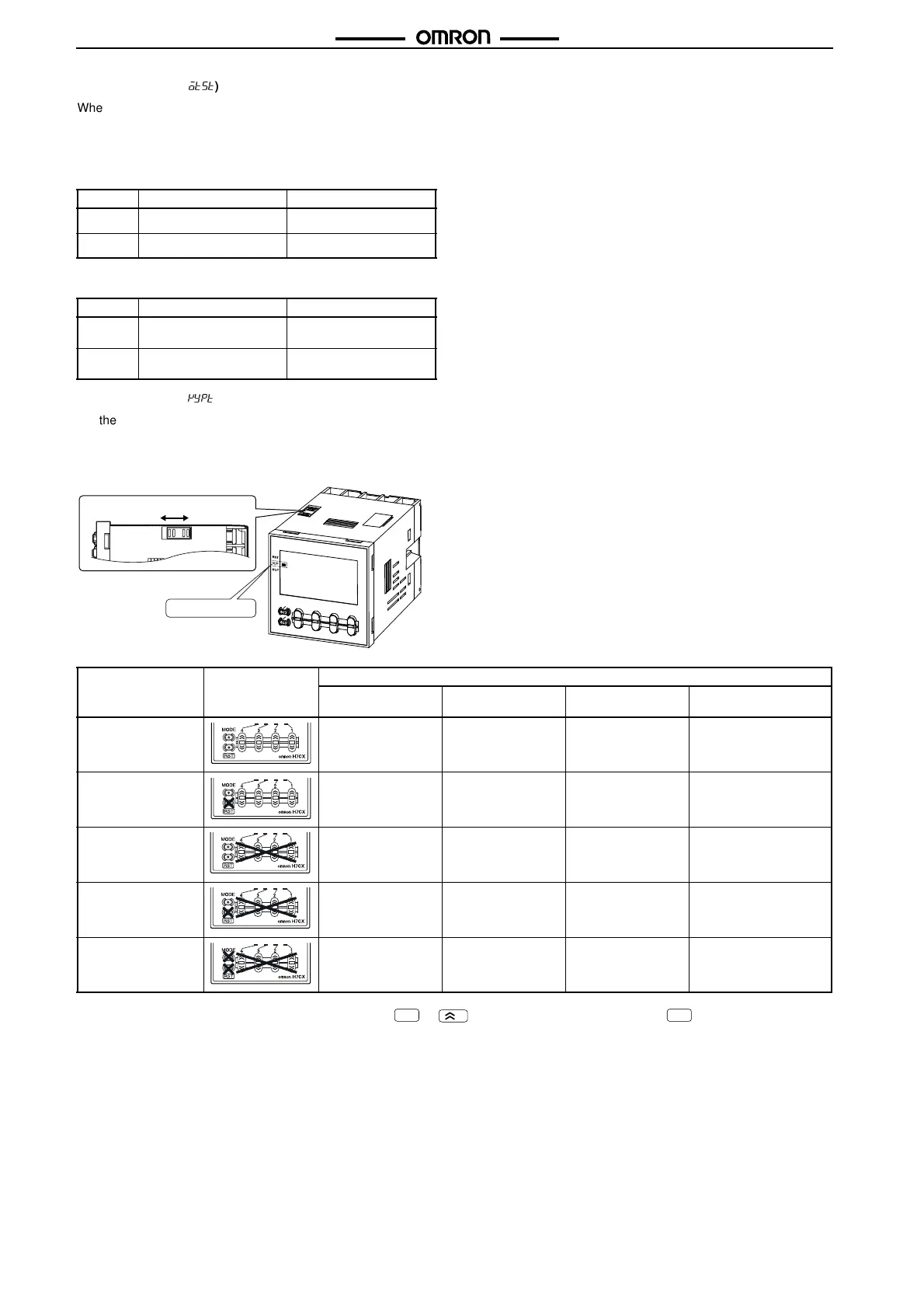
Key Protect Level (
*7/3
)
Set the key protect level.
When the key-protect switch in set to ON, it is possible to prevent setting errors by prohibiting the use of certain operation keys by specify-
ing the key protect level (KP-1 to KP-5). The key protect indicator is lit while the key-protect switch is set to ON. Confirm the ON/OFF status
of the key-protect switch after the H7CX is mounted to the panel.
Note: Changing mode to configuration selection mode ( + 1 s min.) or function setting mode ( 3 s min.).
OUT1 OUT2
.%%
Transistor (12-13) Contact (3, 4, 5)
.-
Contact (3, 4, 5) Transistor (12-13)
OUT1 OUT2
.%%
Transistor (12-13) Transistor with diode
(3, 4, 5)
.-
Transistor with diode
(3, 4, 5)
Transistor (12-13)
Level Meaning Details
Changing mode
(See note.)
Switching display
during operation
Reset key Up/down key (Up key
for 6-digit models)
KP-1 (default setting) No Yes Yes Yes
KP-2 No Yes No Yes
KP-3 No Yes Yes No
KP-4 No Yes No No
KP-5 No No No No
Note: Factory-set to OFF
Key protect indicator
(See note)
1
MODE

 Loading...


