H7CZ
5
Connections
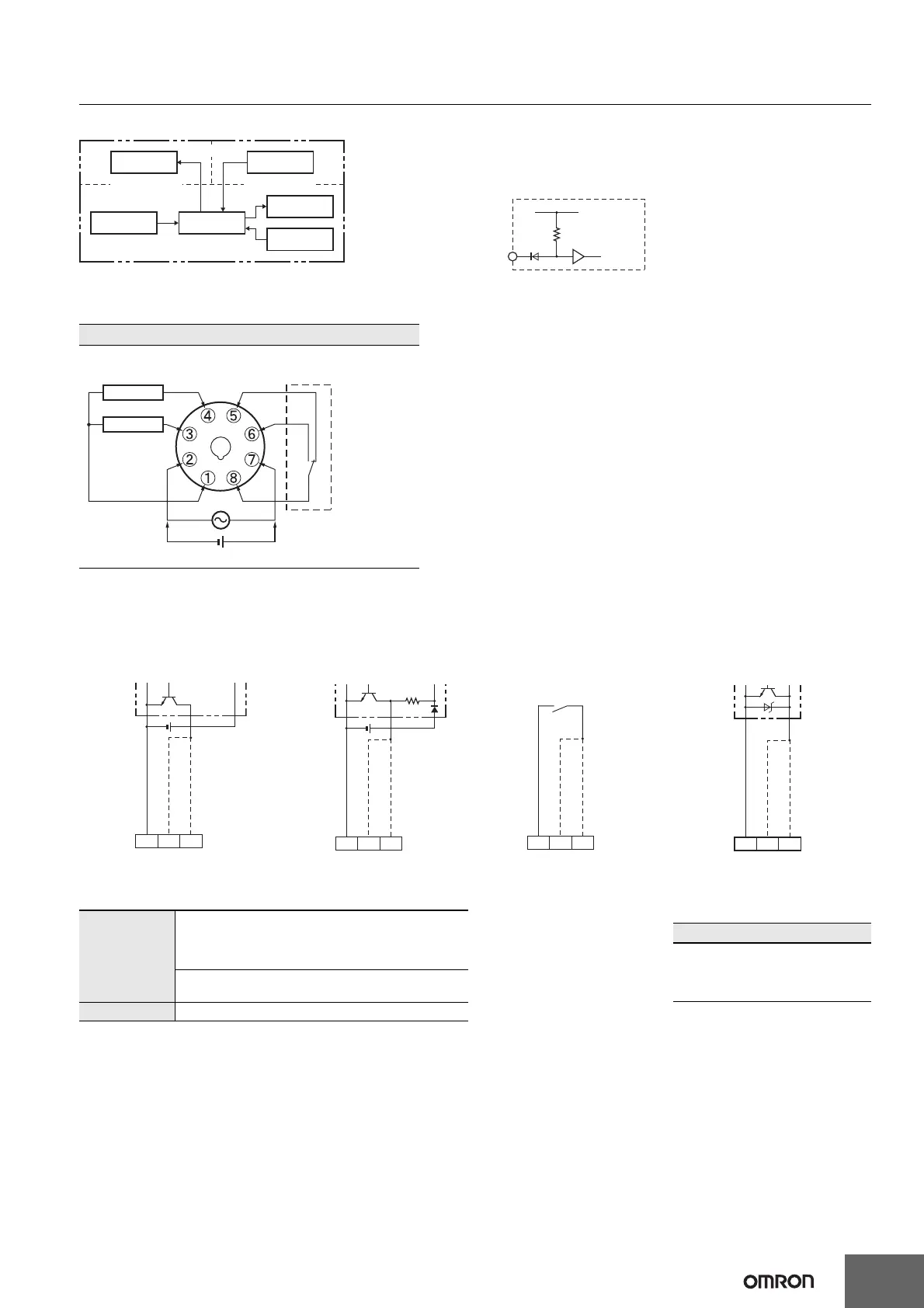
Block Diagram
Terminal Arrangement
Confirm that the power supply meets specifications before use.
Input Circuits
Count and Reset Input
Input Connections
The inputs of the H7CZ-L8@ are no-voltage (short-circuit or open) inputs.
No-voltage Inputs (NPN Inputs)
No-voltage Input Signal Levels
Note: The DC voltage must be 30 VDC max.
H7CZ-L8/L8D1
1-stage Contact Output
Output circuit
Display circuit
Input circuits
(Basic insulation)
(Basic insulation)
Internal
control circuit
Power supply
circuit
Key switch
circuit
(Basic insulation)
0V
Count
Internal circuit
Contact Output
Reset
(+) (−)
No-voltage Inputs (NPN Inputs)
Internal
circuit
IN
+14V
1 kΩ
Open Collector Voltage Output Contact Input DC Two-wire Sensor
Note: Operates with transistor ON.
PLC or
sensor
134
0 V for inputs
Reset input
Count input
Note: Operates with transistor ON.
Sensor
0 V for inputs
134
Reset input
Count input
Note: Operates with relay ON.
0 V for inputs
134
Reset input
Count input
Note: Operates with transistor ON.
0 V for inputs
134
Reset input
Count input
No-contact input
Short-circuit level (transistor ON)
• Residual voltage: 3 V max.
• Impedance when ON: 1 kΩ max.
(The leakage current is approx. 12 mA when the impedance is 0 Ω.)
Open level (transistor OFF)
• Impedance when OFF: 100 kΩ min.
Contact input Use contacts which can adequately switch 5 mA at 10 V.
Applicable Two-wire Sensor
• Leakage current: 1.5 mA max.
• Switching capacity: 5 mA min.
• Residual voltage: 3 VDC max.
• Operating voltage: 10 VDC

 Loading...