3
H8CA-SH8CA-S
Engineering Data
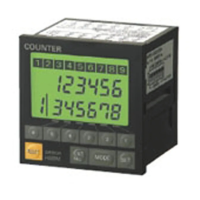
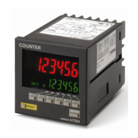
■ ELECTRICAL SERVICE LIFE
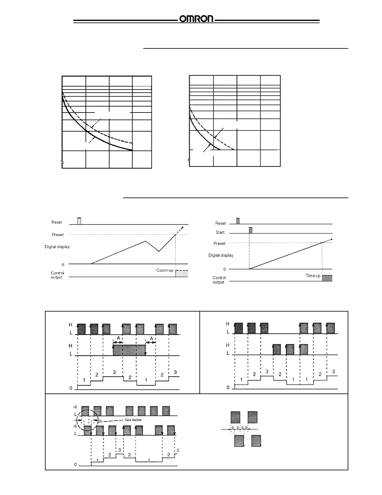
Timing Charts
Resistive Load Inductive Load
■ IN COUNTER FUNCTION MODE
■ COUNT INPUT MODES
In the timing charts below, "A" is the minimum signal width. "B" must be at least 1/2 of minimum signal width, otherwise, signals may not
be counted if the miniums for "A" and "B" are not met.
Count
input 1
Count
input 2
Digital
display
Command Input Mode A
Count
input 1
Count
input 2
Digital
display
Phase Difference Input Mode C
Count
input 1
Count
input 2
Digital
display
Individual Input Mode B
Counting speeds of CP1 and CP2 must
be the same for Reversible C.
Enlargement from left.
■ IN TIMER FUNCTION MODE
Switching operations (x10
3
)
30 VDC (p.f. = 1)
250 VAC (p.f. = 1)
1000
500
100
0
0 1 2 3
Load current (A)
30 VDC (L/R = 7 ms)
1000
500
100
0
0 1 2 3
250 VAC
(p.f. = 0.4)
Switching operations (x10
3
)
Load current (A)
 Loading...