K2CU
K2CU
7
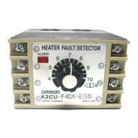
In a Three-phase, V Network 1
Set
the operating current to be 0.3 to 0.35 times the heater current.
Close the SW
2
with switch SW
1
turned on. Confirm that the alarm
indicator remains of
f.
Turn off SW1 and confirm that the alarm indicator comes on, and
that
the output relay operates.
G+
G–
S1
S2
K2CU-F
Heater
SW
1
SSR
SW
2
In a Three-phase, V Network 2
Set
the operating current to be 0.6 times the heater current (of
the
phase connected between terminals 1 and 2, or the one passed
through
the window
of the window-type Current T
ransformer of the
heater
burnout detector).
Close the SW
2
with switch SW
1
turned on. Confirm that the alarm
indicator remains of
f.
Turn off SW1 and confirm that the alarm indicator comes on, and
that
the output relay operates.
G+
K2CU-F
Heater
SSR
SW
2
SW
1
G–
S1
S2
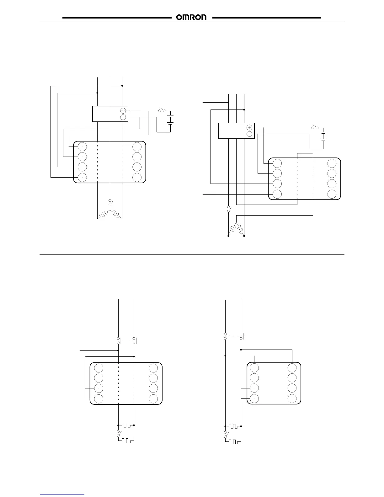
K2CU-F, K2CU-P
The
operation of the heater burnout detector can be easily
checked
as
follows:
In a Single-phase Circuit
Set
the operating current to be 0.55 to 0.6 times the heater current.
Close the contactor with switch SW
1
turned on. Confirm that the
alarm
indicator remains of
f.
Turn
of
f SW
1
and confirm that the alarm indicator comes on, and that
the
output relay operates.
K2CU-F
S1
S2
Heater
SW
1
1
2
K2CU-P
Heater
SW
1
Contactor
Contactor