K2CU
K2CU
9
S1
S2
Heater
K2CU-F
SW
1
Contactor
K2CU-F
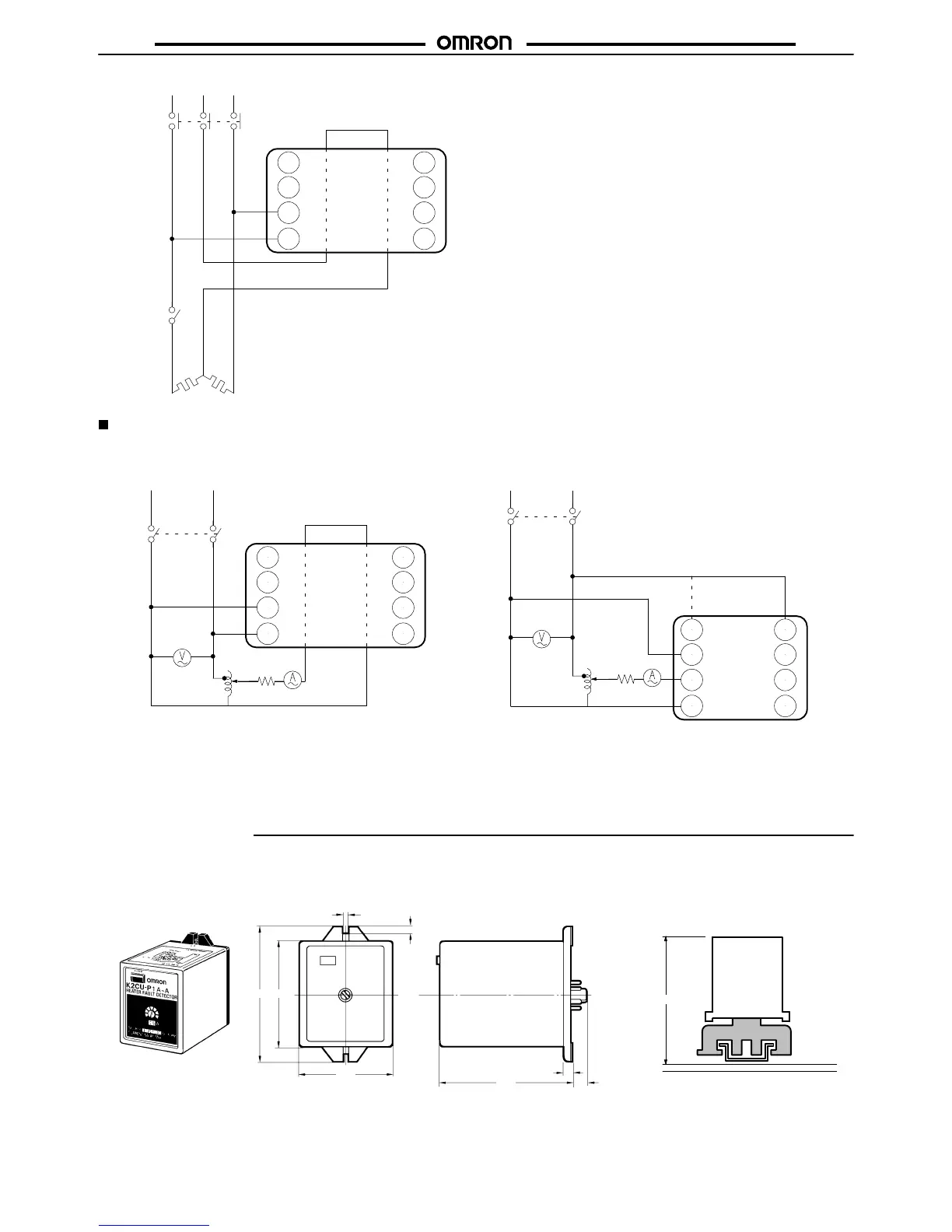
Test Circuit
To
check the operation in detail, use the following circuit.
S1
S2
b1
CM1
a1
Slidac
K2CU-F
SW
1
R
Slidac
Switch
R
1
2
7
8
6
5
4
3
K2CU-P
Switch
The dotted lines indicate the line con-
ductor passing through the round
window of the current transformer.
Note: Determine
the value of R according to the specifications
of the K2CU to be used. The dotted line indicates the
connection at a supply voltage of 100 or 1
10 V
AC.
K2CU-F K2CU-P
Dimensions
Note:
All units are in millimeters unless otherwise indicated.
K2CU-P
Connecting Socket
K2CU-P
8PFA1
108
89
7
8.5
60
7291
3.5
5