K2CU
K2CU
6
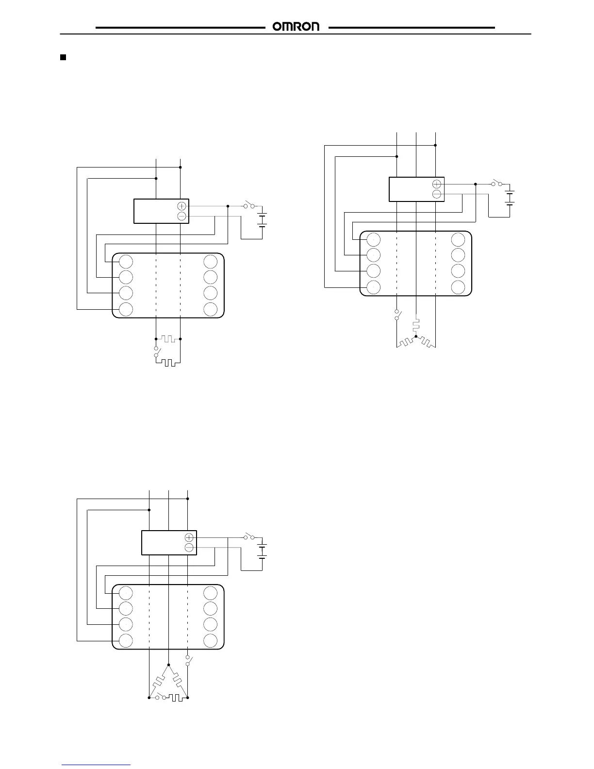
Operation Check
K2CU-F A- GS
The
operation of the heater burnout detector can be easily
checked
as
follows:
In a Single-phase Circuit
Set
the operating current to be 0.6 to 0.55 times the heater current.
Close the SW
2
with switch SW
1
turned on. Confirm that the alarm
indicator remains of
f.
Turn
of
f SW
1
and confirm that the alarm indicator comes on, and that
the
output relay operates.
K2CU-F
S1
S2
G+
G–
Heater
SW
1
SSR
SW
2
In a Three-phase, Delta Network
Set the operating current to be 0.6 times the heater current.
Close
the SW
3
with switches SW
1
and SW
2
turned
on. Confirm that
the
alarm indicator remains of
f.
Turn
of
f SW
2
and confirm that the alarm indicator comes on, and that
the
output relay operates.
Turn
on SW
1
set the operating current to be 0.9 times the heater cur
-
rent, and confirm that the alarm indicator goes off and the output
relay
releases.
Turn
of
f SW
1
and confirm that the alarm indicator comes on, and that
the
output relay operates.
G+
G–
S1
S2
K2CU-F
Heater
SW
1
SSR
SW
3
SW
2
In a Three-phase, Star Network
Set the operating current to be 0.9 times the heater current.
Close the SW
2
with switch SW
1
turned on. Confirm that the alarm
indicator remains of
f.
Turn
of
f SW
1
and confirm that the alarm indicator comes on, and that
the
output relay operates.
G+
G–
S1
S2
K2CU-F
Heater
SW
1
SSR
SW
2