K2CU
K2CU
5
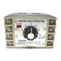
Setting of Operating Current
Use the potentiometer on the front panel to set the operating cur-
rent.
Rotate
the knob to set the desired current value at which the
Heater
Burnout
Detector should operate. Do
not exceed the maximum and
minimum
positions.
The K2CU-F’s scale is divided into 12 graduations including sub-
graduations
and the K2CU-P’
s scale is divided into 5 graduations.
The
knobs of
the K2CU-F and K2CU-P as shown in the illustrations
are
set to 32 A and 0.7 A respectively
.
The
set operating current is defined as the mean value
of the heater
current under normal operating conditions and the heater current
under
a burnout or abnormal condition.
Set value =
Normal current + abnormal current
2
Knob
Red point
(indicates the set value)
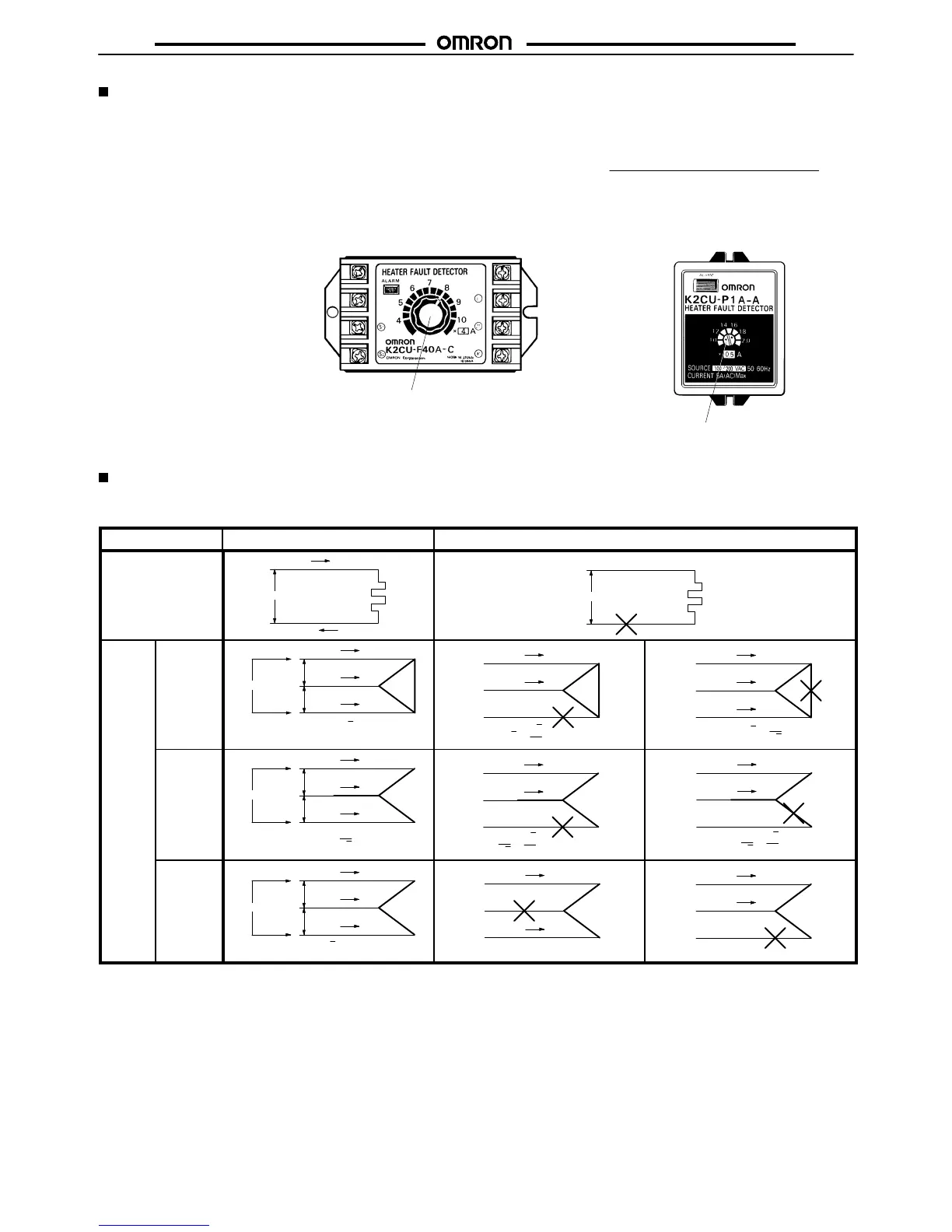
Heater Connection and Current
The
following table shows the dif
ferent connections possible. The formula under each illustration indicates the electrical current value of
the
heater
elements under normal and abnormal conditions.
Phase
Normal condition
Abnormal condition
Single phase
200 V
5 A
5 A
1 kW
200 V
0 A
0 A
Three
phase
Delta
network
200 V
200 V
200 V
8.7 A
8.7 A
8.7 A
1 kW
1 kW
1 kW
(5 A x )
3
7.5 A
7.5 A
3
2
(5 A x x )
3
5 A
8.7 A
5 A
1
3
(5 A x x )
3
Star
network
200 V
200 V
200 V
2.9 A
2.9 A
2.9 A
1 kW
1 kW
1 kW
1
3
(5 A x )
2.5 A
2.5 A
3
2
(5 A x x )
1
3
2.5 A
2.5 A
3
2
(5 A x x )
1
3
V
network
200 V
200 V
200 V
5 A
8.7 A
5 A
1 kW
1 kW
(5 A x = 8.7 A)
3
(5A x 1/2)
2.5 A
2.5 A
5 A
5 A
(5A x 1)
Note: Values
in this table are correct when a 200 V
AC, 1 kW heater is used on a single-phase or three-phase current.