K2CU
K2CU
4
K2CU-F
Series
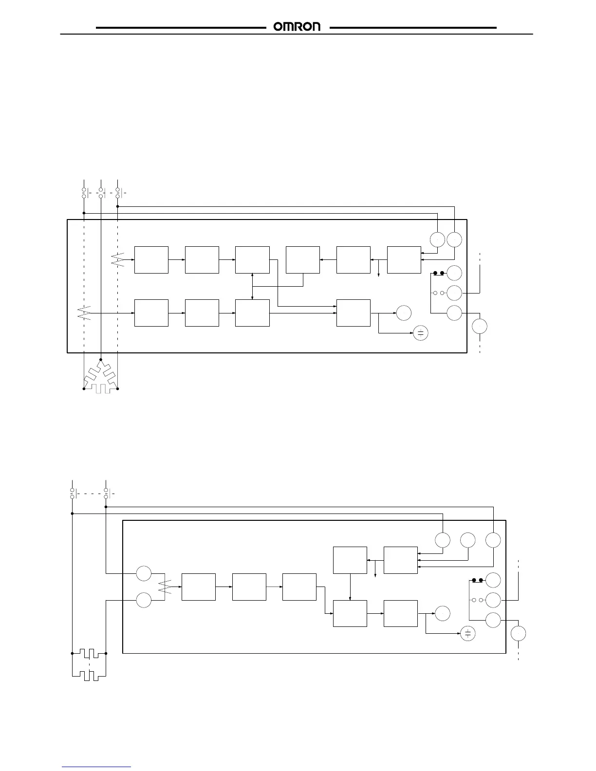
When
power is supplied to the heater (when the contactor
is ON), a
current flows through the wires to the heater elements. At the same
time,
a voltage is imposed on the power circuit of the K2CU-F
.
The current flowing to the heater wires is detected by the detector
sections through each Current Transformer (CT) incorporated by
the K2CU-F.
The
current signals transmitted by the two CT
s are sent to the cur
-
rent-voltage converters, smoothing circuits, and comparators as
shown
in the diagram.
The
signal generated by the reference voltage generator is sent to
the
setting circuit to provide a reference value. The reference value
is sent to the comparators. Each comparator compares its heater
element
current input
and the reference value. If the input is lower
than the reference value, a signal is sent to the output circuit.
There
are two
detector sections operating independently
. If either of
the
input signals from the CT
s is lower than the reference value, the
output
relay and alarm indicator will be activated.
The
K2CU-F incorporates a voltage
fluctuation compensation func
-
tion which automatically corrects the reference value if the supply
voltage
fluctuates.
Current-
voltage
converter
Smoothing
circuit
Setting
circuit
Reference
voltage
generator
Power
circuit
Current-
voltage
converter
Smoothing
circuit
BZ
Output
circuit
X CM1
a1
b1
S2S1
CT
1
CT
2
Heater elements
Power source
X/c
Output relay
Alarm indicator
Buzzer
To each circuit
Comparator
Comparator
Note: The
dotted lines indicate the line conductors passing through the windows of the current transformers.
Contactor
K2CU-P
Series
The
K2CU-P operates basically in the same way as the K2CU-F
.
The comparator compares external current signals and the refer-
ence value and outputs the result of the comparison to the output
circuit.
Current-
voltage
converter
Smoothing
circuit
Setting
circuit
Power
circuit
BZ
Output
circuit
X
3
4
5
87
Comparator
Reference
voltage
generator
Heater elements
Power source
X/c
Output relay
Alarm indicator
To each circuit
Contactor
6
Buzzer
CT
1
2
200/220 V 100/110 V 0 V