EasyManua.ls Logo

Omron E2C User Manual

Omron E2C
24 pages
To Next Page IconTo Next Page
Page #1 background imageLoading...
Page #1 background image
1
Inductive Proximity Sensor E2C
Variable Sensing Distance and
Differential Travel Allow a Wide Range
of Applications
Various Sensing Heads available in outer diame-
tersfrom2.0to40mm.
Operation and stability indicators (LED) in Amplifier
Unit allow easy monitoring of stable operation.
Amplifier Unit has wide-ranging operating voltages,
10 to 30 VDC or 90 to 264 VAC.
Small differences in size, distance, and materials
can be detected.
Ordering Information
AC 2-wire Models
Size Shield Sensing
d
i
t
Maxi- Sensor
H
d
Amplifier Unit
g
distance mum
operat-
ing dis-
tance
Head
Multi-function Single-function Self-
diag-
nostic
function
AC DC
(PNP,
NPN)
DC
(NPN)
DC
(PNP,
NPN)
DC
(NPN)
DC
(PNP)
DC
(NPN)
2.0 dia. Un-
shielded
(see
note1)
0.5 mm 1.2 mm E2C-
CR5B
E2C-
AK4A
E2C-
AM4A
--- --- E2C-
GE4B
E2C-
GF4B
---
3.5 dia.
Shielded
0.8 mm 1.8 mm E2C-
CR8A
E2C-
JCA4
E2C-
WH4AF
(
E2C-
GE4A
E2C-
GF4A
E2C-
JCA4P
(
3.8 dia.
1mm 2mm
E2C-
CR8B
J
C
(see
note 2)
E
2
C
-
G
G
J
C
(see
note 3)
M5 E2C-
X1A
E
2
C
-
WH4A
5.4 dia. E2C-
C1A
M8 1.5 mm 3mm E2C-
X1R5A
M12 2mm 5mm E2C-
X2A
--- --- ---
M18 5mm 10 mm E2C-
X5A
M30 10 mm 18 mm E2C-
X10A
40 dia. Un-
shielded
20 mm 50 mm E2C-
C20MA
Note:
1. The E2C-CR5B cannot be flush-mounted in metal even though the E2C-CR5B is of a shielded construction.
2. Use the E2C-WH4AF in combination with the S3D8 Sensor Controller
3. The E2C-JCA4P is an Amplifier Unit with self-diagnostic output for DIN track mounting.
Question and Answer IconNeed help?

Do you have a question about the Omron E2C and is the answer not in the manual?

Omron E2C Specifications

General IconGeneral
BrandOmron
ModelE2C
CategorySecurity Sensors
LanguageEnglish

Summary

Ordering Information

Sensor Head Specifications

Key Sensor Head Parameters

Technical specifications including sensing distance, response frequency, and environment resistance.

Amplifier Unit Specifications

Cable Length Compatibility

Table detailing compatible cable lengths for amplifier and sensor head combinations.

Operation and Output Circuits

Output Circuit Diagrams

Electrical diagrams illustrating output configurations for various amplifier units.

Operating Charts and Functions

Operating Charts

Charts showing sensor operation based on mode selector and sensing object status.

Self-Diagnostic Function

Explanation of the self-diagnostic output feature and its indicators.

Indicators and Sensitivity Adjustment

Indicator Functions

Explanation of operation and stability indicators for sensing object detection.

Initial Sensitivity Adjustment

Steps for initial sensitivity adjustment using indicator feedback without a sensing object.

Engineering Data

Typical Operating Range Charts

Graphical data illustrating typical sensing ranges for various sensor models against object size.

Nomenclature and Model Settings

E2C-Gj 4j Model Settings

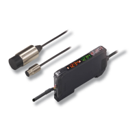
Settings and nomenclature for the E2C-Gj 4j single-function model.

E2C-JC4A Model Settings

Settings and nomenclature for the E2C-JC4A multi-function model.

E2C-JC4AP Model Settings

Settings and nomenclature for the E2C-JC4AP self-diagnostic output model.

Cable Length Compensation

E2C-WH4A(F) Compensation Settings

Cable length settings for the E2C-WH4A(F) multi-function model.

E2C-Aj 4A Compensation Settings

Cable length settings for the E2C-Aj 4A multi-function model.

Sensor Dimensions

E2C-CR5B Dimensions

Dimensional drawings and specifications for the E2C-CR5B sensor.

Further Sensor Dimensions

E2C-X5A Dimensions

Dimensional drawings and specifications for the E2C-X5A sensor.

Amplifier Unit Dimensions

E2C-AM4A Dimensions

Dimensional drawings and specifications for the E2C-AM4A amplifier unit.

Installation and Connection

Amplifier Unit Wiring Diagrams

Wiring diagrams for connecting various OMRON E2C amplifier units.

Load Connection Examples

E2C-GE4j Load Connection

Diagrams illustrating load connection methods for the E2C-GE4j amplifier unit.

Load Connection Examples (Continued)

E2C-WH4A(F) Load Connection

Load connection examples for the E2C-WH4A(F) amplifier unit with different load types.

Accessories and Mounting Sockets

Connecting Socket Models

List and types of sockets available for connecting E2C amplifier units.

Socket Mounting and Panel Cutouts

P3GA-11 Socket Details

Terminal arrangement and mounting dimensions for the P3GA-11 socket.

Socket Mounting Options

PL08 Socket Details

Terminal arrangement and mounting holes for the PL08 socket.

Precautions and Interference

Mounting Precautions

Guidelines for proper mounting torque, screw tightening, and tool usage.

Mutual Interference

Minimum distances required to prevent mutual interference between E2C units.

Amplifier Unit Mounting Procedures

E2C-JC4A Mounting

Instructions for vertical and side mounting of the E2C-JC4A amplifier unit.

Amplifier Unit Dismounting and Wiring

Dismounting the Amplifier Unit

Procedures for removing amplifier units using mounting adapters and fixtures.

Related product manuals