E2C
E2C
16
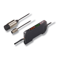
E2C-JC4AP
Operation indicator
Stability indicator
Timer switch
Operating mode selector
Sensitivity adjuster
Caution label (provided with
E2C-JC4AP) (see note 1)
Mounting Bracket
(provided with E2C-JC4AP)
Two, 3.3 dia.
Code (see note3)
Mounting bracket
(provided with E2C-JC4AP)
Note:
1. Paste the caution label after the sensitivity adjustment of the E2C-JC4AP to prevent mis-operation.
2. The mounting bracket will not be required if the E2C-JC4AP is mounted to DIN tracks.
3. Vinyl-insulated round cable with four conductors, 4.5 dia. (18/0.12); standard length: 2 m
1.7 radius
Installation
Connection
E2C-AK4A
Sensor Head
Transistorized
photocoupler
output
P2CF-11
100 to 240 VAC
Relay contact
output
E2C-AM4A
Sensor Head
Shielded cable
P2CF-08
0V
12 to
24 VDC
NPN
output
PNP
output
Shielded cable
Amplifier Unit:
E2C-AK4A
Applicable Socket:
P2CF-11
Amplifier Unit:
E2C-AM4A
Applicable Socket:
P2CF-08
E2C-JC4A
Shield Conductor
Brown (Red)
Black (White)
Blue (Black)
10 to 30 VDC
NPN open collector output
0V
E2C-JC4AP
Shield Conductor
Brown (Red)
Black (White)
Blue (Black)
10 to 30 VDC
NPN open collector output
0V
Orange (Yellow)
Self-diagnostic output
Sensor Head Sensor Head