Timer Interval Indicator K3HB-P 13
Operation
■ Functions (Operating Modes)
F1 to F6
These functions use the internal system clock to measure the time between pulses or the pulse ON time and then display time measurements or
a variety of other calculations.
Function name Function No.
Passing speed f1
Cycle f2
Time difference f3
Time band f4
Measuring length f5
Interval f6
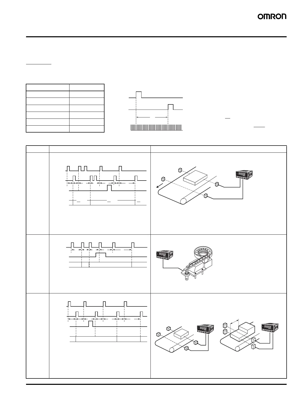
The time (T) between input A pulse and input B pulse
is measured by the internal system clock. If, for
example, the system clock measures 100,000 counts
during time T, then
T = 1 system clock count (0.5
µs) × 100,000
T = 0.05 s
F1 (the passing speed) is calculated internally
using the formula
× 60 (m/min), and the
display, in this example, would be
× 60=
1200 (m/min).
1
T
1
0.05 s
Input A
Input B
Internal
system clock
1
1
T
Example: F1 Passing Speed
Function Operation Operation image (application)
F1
Passing
speed
The reciprocal of the time (T) from input A ON to input
B ON is multiplied by 60 and displayed.
• Recovery time (T
R
) of 20 ms is required before
starting the next measurement.
Display unit:
mm/s, m/s
m/min, km/h, etc.
Measuring workpiece passing speed between A and B
F2
Cycle
Measures and displays input A cycle (T).
Display unit:
ms, s, min.,
min.s.1/10 s
Measuring feed cycles for parts
F3
Time dif-
ference
Displays the time (T) from input A ON to input B ON.
• Recovery time (TR) of 20 ms is required before
starting the next measurement.
Display unit:
ms, s, min.,
min.s.1/10 s
Input A
Input B
Display
HOLD input
TRT1 TR
T2 TR T3 T4
T1
1
× 60
T2
1
× 60
T4
1
× 6
æ
ç
ç
è
ö
÷
÷
ø
A
B
Input A
Display
HOLD input
T1
T1 T2 T5
T3 T4 T5T2
Measurement range: 20 ms to 3,200 s
æ
ç
ç
è
ö
÷
÷
ø
Input A
Input B
Display
HOLD input
T1 TR TR TR
T1 T3 T4
T2 T3 T4
Measurement range: 10 ms to 3,200 s
æ
ç
ç
è
ö
÷
÷
ø
A
B
Measuring workpiece passing time
between A and B
easur
ng t
e
engt
o
a
workpiece step by changing
prescale values.

 Loading...