11-6
Accessories Section 1-3
BCD
Communications
• In Setup Mode, all BCD data turns OFF.
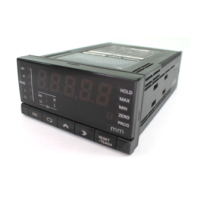
• When the POL signal is ON, the polarity is negative. When the polarity
signal is OFF, the polarity is positive.
• The OVER signal is output when there is a BCD data overflow or under-
flow. At that time, the display of the Digital Indicator displays flashing
numeric values.
• In Test Mode, the display value that is currently keyed in is output for the
REQ signal, MAX signal, or MIN signal.
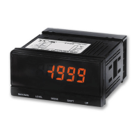
• The REQ signals from two or more Digital Indicators cannot be input at
the same time. Use wired OR connections and offset the timing of REQ
signal inputs.
1-3 Accessories
1-3-1 Connectors (Included)
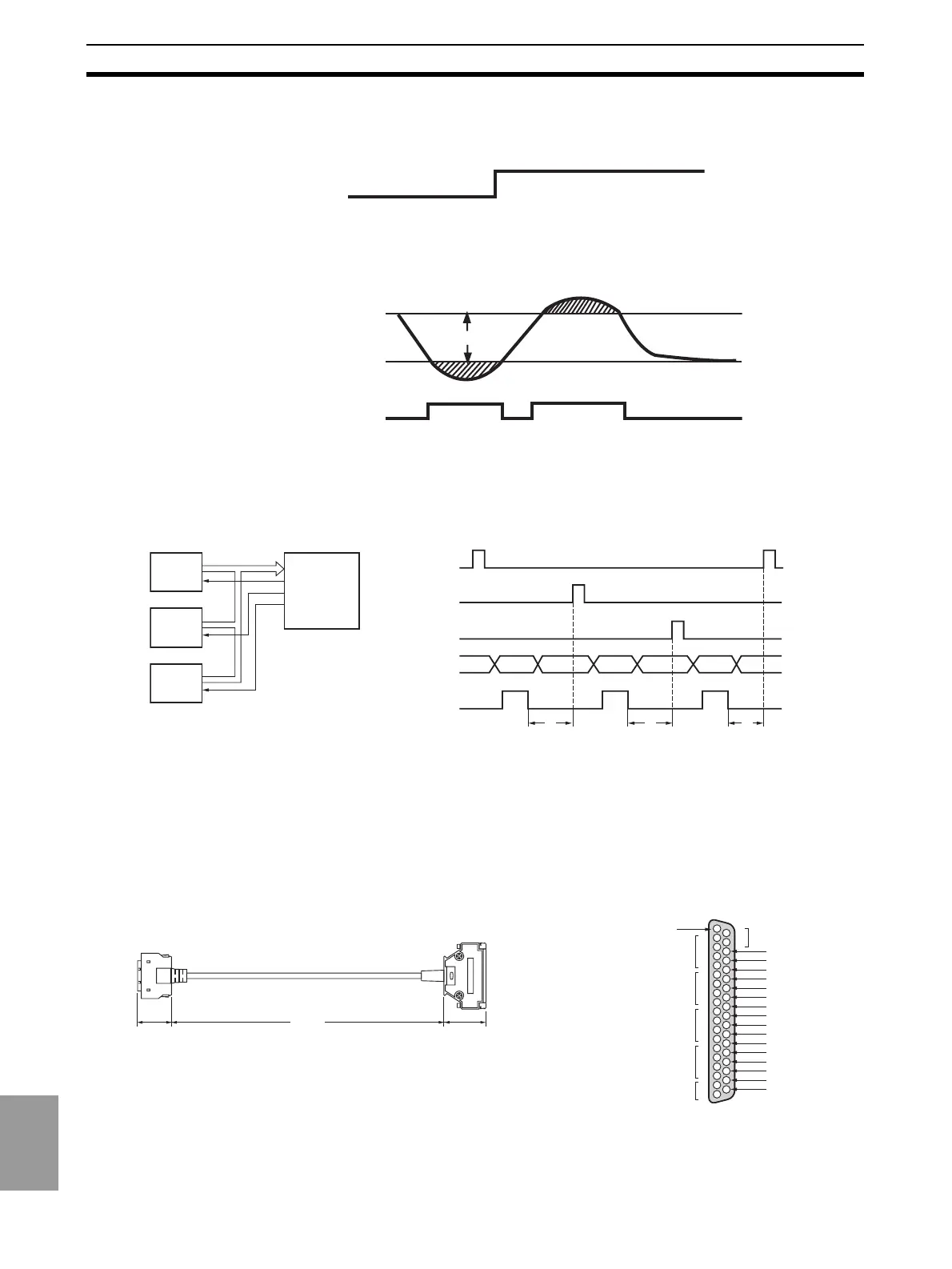
1-3-2 Cable: K32-BCD
Note D-sub connectors are connected to the BCD output cable.
Cover: 17JE-37H-1A (made by DDK)
Connector: 17JE-23370-02(D1) (made by DDK) suitable product
POLARITY
(+) OFF
(−) ON
Permissible span
Input
Underflow
Overflow
OVER
K3HB
(1)
K3HB
(2)
K3HB
(3)
Programmable
Controller
DATA (including POL and OVER)
Use a wired OR for DATA VALID.
RUN, HH (OUT5), H (OUT4),
PASS (OUT3), L (OUT2), and LL
(OUT1) are always output,
regardless of the REQ signal.
Do not use a wired OR.
DATA
REQ. (1)
(1) (2) (3)
REQ. (2)
REQ. (3)
DATA
VALID
* * *
*Maintain a 20 ms interval from when DATA VALID turns OFF to the next REQ si
nal.
38 mm 46.5 mm
300 mm
K3HB end
Connecting device end
(PLC, display, etc.)
Cover: HDR-ES0LPA5 (made by Honda Tsushin Kogyo Co., Ltd.)
Connector: HDR-ES0MAG1 (made by Honda Tsushin Kogyo Co., Ltd.)
D-sub connector (37-pin, female)
Cover: 17JE-37H-1A (made by DDK)
Connector: 17JE-13370-02(D1) (made by DDK) applicable product
Stud: 17L-002A (made by DDK)
External View
1
2
3
4
5
6
7
20
21
22
23
24
25
26
27
28
29
30
31
32
33
34
35
36
37
10
0
10
1
10
2
10
3
10
4
10
4
OVER
DATA VALID
RUN
COMMON
REQUEST
MAX REQ.
MIN REQ.
HOLD (COMPENSATION)
RESET
POLARITY
HH (OUT5)
H (OUT4)
PASS (OUT3)
L (OUT2)
LL (OUT1)
COMMON
1
2
4
8
1
2
4
8
1
2
4
8
1
2
4
8
1
2
COMMON
4
8
7
8
9
10
11
12
13
14
15
16
17
18
19
Pin Wiring Diagram

 Loading...