4-3
Introduction Section 2-1
Operating
Procedures
Note (1) When changing the baud rate of the master after starting the K3HB-DRT
Digital Indicator, turn ON the communications power supply of the Digital
Indicator again, and restart the Digital Indicator.
When setting the Configurator only, without a master, the baud rate of the
Configurator will be automatically detected.
(2) The following points are important when editing device parameters using
the Configurator.
• It is recommended that device default values are uploaded before the
parameters are edited because the EDS parameter defaults and the
device defaults are different.
• The setting for some parameters are different for the list of settings
provided in the CompoWay/F SECTION 2 List of Settings. For exam-
ple, the parameter setting for input type A is different for each model.
• Set the unit number in the Communications Setting Level parameter
group to change the node address.
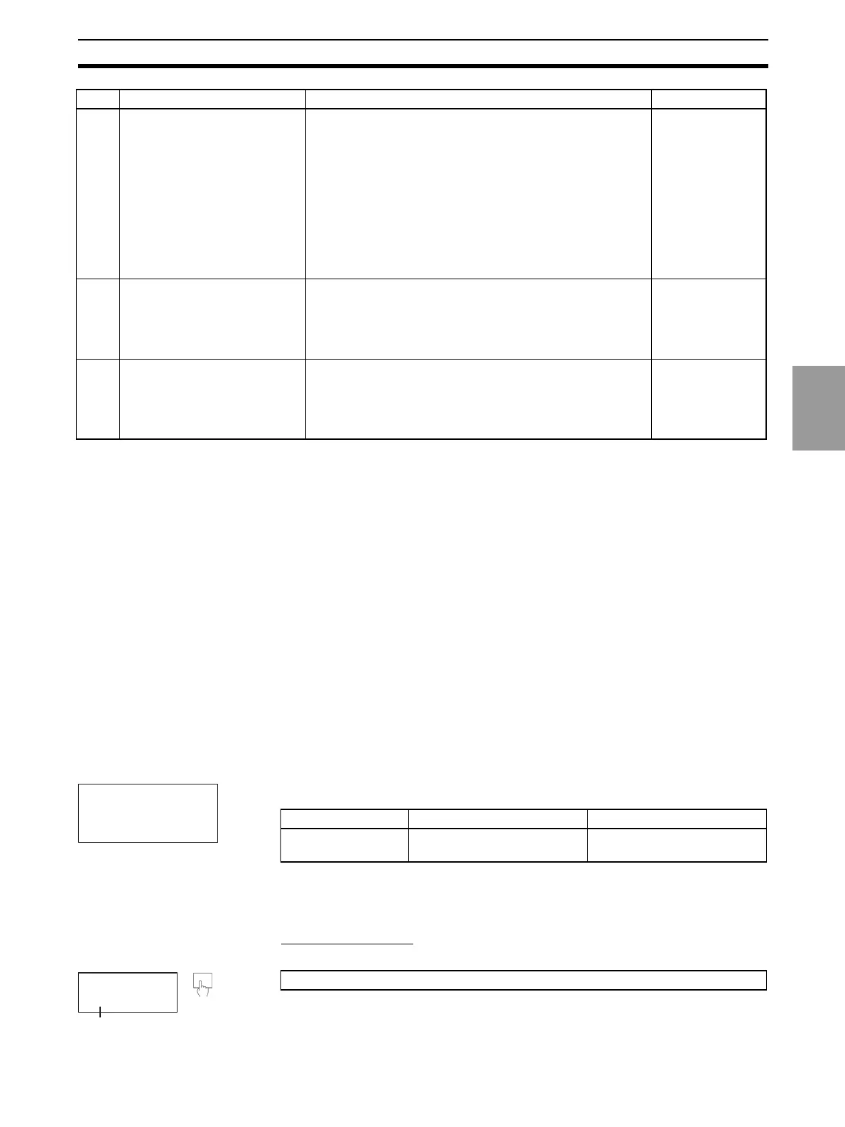
2-1-3 Setting Node Addresses
DeviceNet node addresses are set in the communications setting level. Set
the node addresses on the front panel of the K3HB-DRT.
Note The node address will be 0 if an address between 64 and 99 is set.
Setting Parameters
• The initial setting level is indicated by L0 being displayed in the level/bank
display.
10 Operate from the Configurator. Set from the Configurator when changing data allocated in
the IN and OUT Areas from the default values.
To split the IN Area used by the K3HB-DRT into two areas,
select K3HB-DRT in the master’s Edit Device Parameters
Window and set the connection in the detailed settings.
When the IN Area is split into two areas, for example, oper-
ating parameters, such as measurement values and com-
parative set values, can be allocated in IN Area 1, and
status values can be allocated in IN Area 2. For example, IN
Area 1 can be allocated in the DM Area and IN Area 2 can
be allocated in the CIO Area.
SECTION 4
Remote I/O Com-
munications
11 Start remote I/O communica-
tions.
Enable the master’s scan list and change the PLC to RUN
Mode.
Remote I/O communications will start, and the contents of
the IN and OUT Areas in the master and K3HB-DRT Digital
Indicator will be synchronized.
---
12 Use explicit message commu-
nications.
Send explicit messages from the master.
Explicit messages can be used to perform control and mon-
itoring that cannot be achieved using the IN and OUT Areas
alone, by sending explicit messages to the K3HB-DRT Digi-
tal Indicator.
SECTION 5
Explicit Message
Communications
Step Item Details Reference
U-NO
u-no
L
6
Parameter Setting value Meaning
Unit No.
u-no
0 to 99 0 to 99 (See note.)
L
0
L0 is displayed.
At least 3 s
A. Press the LEVEL Key for at least 3 s to move to the input initial setting level.

 Loading...