EasyManua.ls Logo

Omron K7L-AT50 User Manual

Omron K7L-AT50
4 pages
To Next Page IconTo Next Page
Page #1 background imageLoading...
Page #1 background image
Liquid Leakage Sensor Amplifier K7L-AT50 3
Liquid Leakage Sensor Amplifier
K7L-AT50
Ultra-miniature Sensor Amplifier Reliably
Detects a Wide Variety of Liquids Ranging
from Water to Liquid Chemicals with Low
Conductivity.
Detects liquids with impedance as high as 50 M using inter-
electrode resistance detection. Detection of IPA and pure water
is possible.
Four selectable sensing ranges ensure detection suited to the
characteristics of the liquid.
Incorporates a noise canceller circuit connected to a 3-conduc-
tor cable, ensuring a high level of noise immunity and reliable
operation (patent pending).
The power supply block and Sensing Band are isolated, allow-
ing the installation of more than one device in the same place.
Ordering Information
Note: 1. Compared with the standard model, F03-16PE.
2. One F03-20 Terminal Block is included as an accessory with the K7L-AT50.
3. The minimum order for the F03-25, F03-26PES, or F03-26PEN Sensing Band Stickers is one set (contains 30 Stickers).
4. The minimum order for F03-20 Terminal Blocks, F03-26PTN Sensing Band Stickers, or F03-26PS Point Sensor Mounting Brackets is one
set (contains 10 Terminal Blocks, Stickers, or Mounting Brackets).
Available Sensing Band Lengths
Note: 1. To place an order for 1 m of the F03-16PE for example, specify F03-16PE-1M.
2. If you cannot find the length you need, please order the nearest larger length, then cut it to the required size.
Product name Model Characteristics
Liquid Leakage Sensor Amplifier K7L-AT50 ---
Sensors Sensing Band F03-16PE Standard model
F03-15 Greater durability and condensation resistance. (See note 1.)
F03-16PT Greater temperature and chemical resistance. (See note 1.)
F03-16SF Greater flexibility and superior workability. (See note 1.)
F03-16SFC Greater flexibility and enables visual confirmation when the inner color ap-
pears.
Point Sensor F03-16PS Easier to wipe off than the band type.
F03-16PS-F Electrodes have fluororplastic coating to resist chemicals.
Mounting Brackets
and Stickers
Sensing Band Stick-
ers
F03-25 Used for F03-15 or F03-16SF(C).
F03-26PES Used for F03-16PE (adhesive tape).
F03-26PEN Used for F03-16PE (screws).
F03-26PTN Used for F03-16PT (screws).
Point Sensor Mount-
ing Brackets
F03-26PS Used for F03-16PS.
Terminal Blocks F03-20 ---
Track-mounted Socket P2RF-08-E ---
P2RF-08 ---
1 m 2 m 5 m 10 m 15 m 20 m 25 m 30 m 40 m 50 m 60 m 70 m 75 m 80 m 90 m 100 m
F03-16PE OK OK OK OK OK OK OK OK
F03-15 OK OK OK OK OK OK OK OK OK OK
F03-16PT OK OK OK OK OK OK
F03-16SF(C) OK OK OK OK OK OK OK OK OK OK OK OK

Other manuals for Omron K7L-AT50

Question and Answer IconNeed help?

Do you have a question about the Omron K7L-AT50 and is the answer not in the manual?

Omron K7L-AT50 Specifications

General IconGeneral
Ambient temperature-10 to 55°C (with no icing or condensation)
TypeAmplifier
Power supply voltage100-240 VAC, 50/60 Hz
Operating voltage range85 to 264 VAC
Power consumptionApprox. 3.5 VA (at 240 VAC)
Alarm outputSPDT relay, 5 A at 250 VAC (resistive load)
Applicable liquidConductive liquid
Electrode resistance0 to 50 kΩ
Insulation resistance100 MΩ min. at 500 VDC
Storage Temperature-25 to +65°C (with no icing or condensation)
Ambient humidity35% to 85% (with no condensation)
Vibration resistance10 to 55 Hz
Life expectancyElectrical: 100, 000 operations min. (at rated load)

Summary

Ordering Information

Sensors

Lists different sensing band types, point sensors, and their characteristics for ordering.

Mounting Brackets and Stickers

Details mounting accessories for sensing bands and point sensors, including specific types and uses.

Terminal Blocks and Sockets

Covers terminal blocks and track-mounted sockets used for connections.

Specifications

Ratings

Details power supply voltage, operate/release resistance, output configuration, and wiring distance.

Characteristics

Lists ambient conditions, insulation resistance, dielectric strength, power consumption, response time, and weight.

Product Details and Operation

Nomenclature

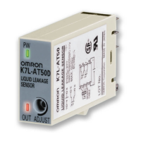
Identifies key components, indicators, and adjustment points of the sensor amplifier.

DIP Switch Settings

Explains how to set the sensing range and output mode using DIP switches.

Operation and Noise Countermeasures

Describes the noise canceller function and connection for inductive noise offset.

Connections and Examples

Connections Overview

Illustrates the wiring diagram showing connections to the sensor amplifier and terminal block.

Connection Examples

Provides wiring diagrams for NPN and PNP output configurations.

Related product manuals