Do you have a question about the Omron SMARTSTEP R7D-AP Series and is the answer not in the manual?
Details the key features and benefits of the SMARTSTEP A-series.
Illustrates how different components connect within the system.
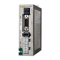
Identifies and explains the parts of the Servo Driver.
Lists relevant safety and compatibility standards.
Provides electrical diagrams for system configurations.
Lists available Servomotor, Servo Driver, and reduction gear models.
Provides physical dimensions for Servo Drivers and mounting details.
Details general, performance, terminal block, and I/O specs.
Details general, performance, and encoder specifications.
Lists specifications and models for reduction gears.
Details specifications for various cables and connectors.
Covers specifications for servo relay units and their connection cables.
Details specifications for the hand-held parameter unit.
Provides specifications for external regeneration resistors.
Lists specifications for DC reactors used for harmonic current control.
Covers space, mounting, operating environment, and impact requirements.
Details connecting cables, terminal blocks, and general wiring practices.
Explains regenerative energy calculation and absorption methods.
Step-by-step guide for mounting, wiring, switch settings, and trial operation.
Explains front panel rotary switches and function switches.
Details checks before turning power ON and indicator checks.
Procedures for no-load, loaded, and actual condition operation checks.
Covers online autotuning and manual tuning for gain adjustment.
Lists and describes Servo Driver internal user parameters.
Explains position control, brake interlock, torque limiting, and gear functions.
Guides on preventive checks, analysis tools, and replacement procedures.
Details Servo Driver alarm display and an alarm table.
Provides error diagnosis based on display and operating status.
Explains overload protection characteristics and related graphs.
Recommends maintenance cycles for Servomotors and Servo Drivers.
Illustrates various connection examples for different controllers.