Chapter 2
2-25
Standard Models and Specifications
■ Control Input Details
● Feed Pulse/Direction Signal, Reverse Pulse/Forward Pulse, +90° Phase Difference
Signals (Phase A/Phase B)
CN1 Pin Numbers
CN1 pin 1:
+Feed Pulse (+PULS), +Reverse Pulse (+CW), +90
° Phase Difference Signals (Phase A) (+A)
CN1 pin 2:
–Feed Pulse (–PULS), –Reverse Pulse (–CW), –90
° Phase Difference Signals (Phase A) (–A)
CN1 pin 3:
+Direction Signal (+SIGN), +Forward Pulse (+CCW), +90
° Phase Difference Signals (Phase B) (+B)
CN1 pin 4:
–Direction Signal (–SIGN), –Forward Pulse (–CCW), –90
° Phase Difference Signals (Phase B) (–B)
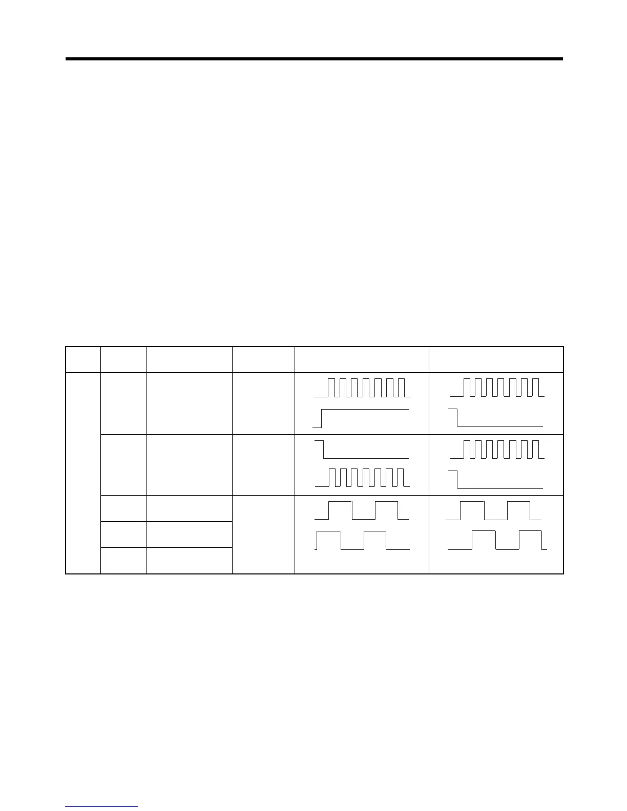
Functions
The function of these signals depends on the setting of Pn200.0 (command pulse mode: position
control setting 1).
Logic Pn200.0
setting
Command pulse
mode
Input pins Servomotor forward
command
Servomotor reverse
command
0 Feed pulse and
direction signal
1: +PULS
2:
–PULS
3: +SIGN
4:
–SIGN
1 Reverse pulse
and forward
pulse
1: +CW
2:
–CW
3: +CCW
4:
–CCW
290
° phase differ-
ence signals (
×1)
1: +A
2:
–A
3: +B
4:
–B
390
° phase differ-
ence signals (
×2)
490
° phase differ-
ence signals (
×4)
Positive
H
L
L
L

 Loading...


