Chapter 4
4-17
Operation
4-6-2 Parameter Details
Setting Explanation
• This parameter sets the Servomotor’s direction of rotation.
Setting Explanation
• Select the stopping method for when the servo is turned OFF or an alarm occurs.
Note 1. If function switch 6 is OFF to enable the function switch settings, this parameter is ignored
and the setting on function switch 2 (dynamic brake setting) is used.
Note 2. If the parameter is set to 0 or 1 and the Servomotor is turned by an external force to 20 r/min
or faster after the dynamic brake has stopped the Servomotor, the Servo ON status will not
be entered even if the RUN signal turns ON.
Note 3. The dynamic brake will operate when the main circuit power supply or the control power sup-
ply is OFF regardless of the setting of this parameter.
Pn402 Forward torque
limit
Forward rotation output torque limit (rated torque ratio) 350 % 0 to 800 –
Pn403 Reverse torque
limit
Reverse rotation output torque limit (rated torque ratio) 350 % 0 to 800 –
Pn500 Positioning com-
pleted range
The range of positioning completed output (INP) 3 Command
units
0 to 250 –
Pn505 Deviation counter
overflow level
The detection level for a deviation counter overflow alarm 1024
×256 com-
mand units
1 to 32767 –
Pn600 Regeneration
resistor capacity
Setting for regeneration resistance load ratio monitoring calculations
Note: If using an External Regeneration Resistor, set the regeneration
capacity for when the temperature rises above 120
°C. If not using an
External Regeneration Resistor, set Pn600 to 0.
0
×10 W From 0
(Varies by
Unit.)
–
Pn000.0 Basic switches 1 – Reverse rotation mode
Settings 0, 1 Unit --- Default 0 Restart? Ye s
Setting Explanation
0 CCW direction is taken for positive command (counterclockwise seen from the Servomotor output
shaft)
1 CW direction is taken for positive command (clockwise seen from the Servomotor output shaft)
Pn001.0 Basic switches 2 – Stop selection for alarm and servo OFF
Settings 0 to 2 Unit --- Default 2 Restart? Ye s
Setting Explanation
0 Stop Servomotor using dynamic brake, dynamic brake stays ON after Servomotor has stopped.
1 Stop Servomotor using dynamic brake, dynamic brake released after Servomotor has stopped.
2 Stop Servomotor using free run.
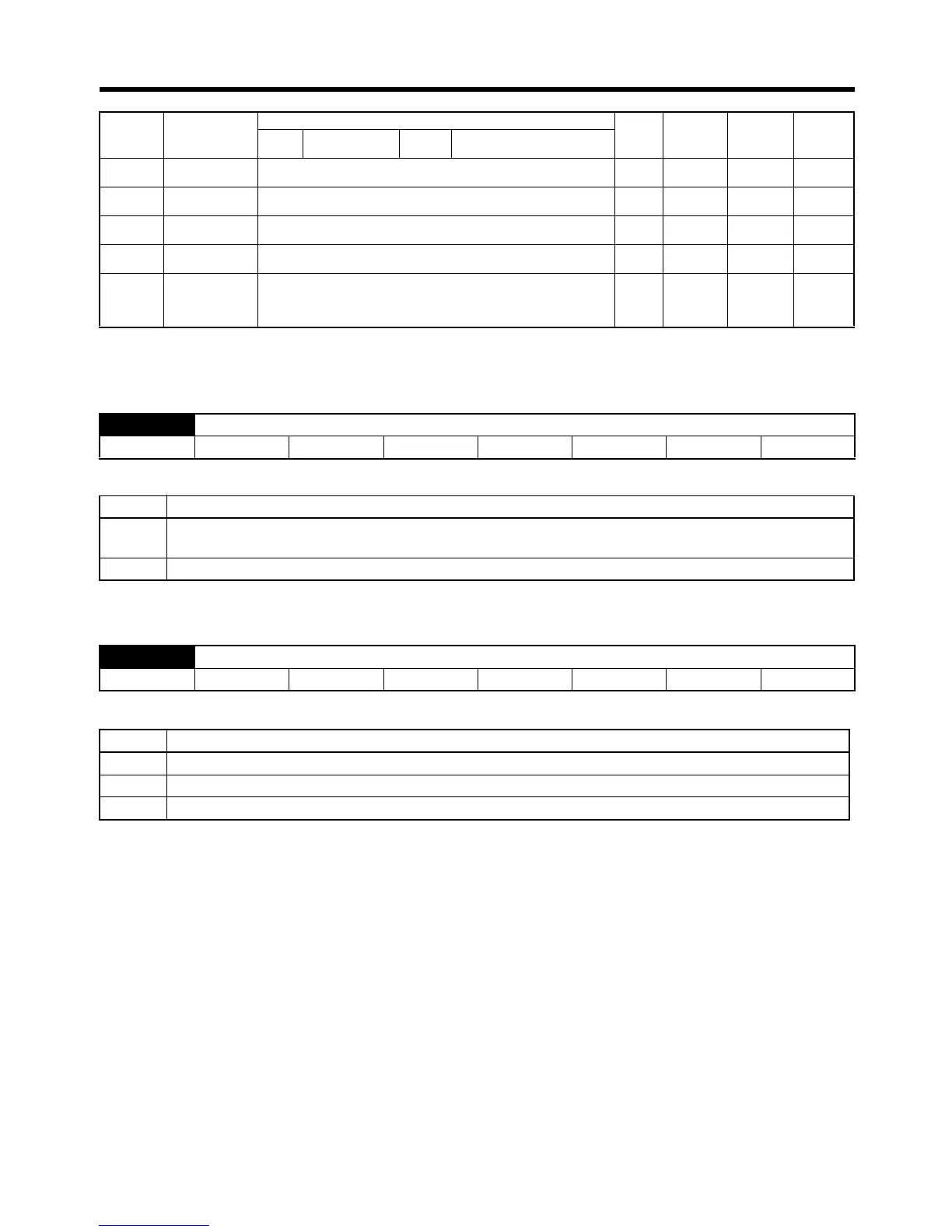
Parameter
No.
Parameter name Description for parameters set with 5 digits Default Unit Setting
range
Restart?
Digit
No.
Name Setting Description for parameters
with individually set digits

 Loading...


