Chapter 6
6-13
Appendix
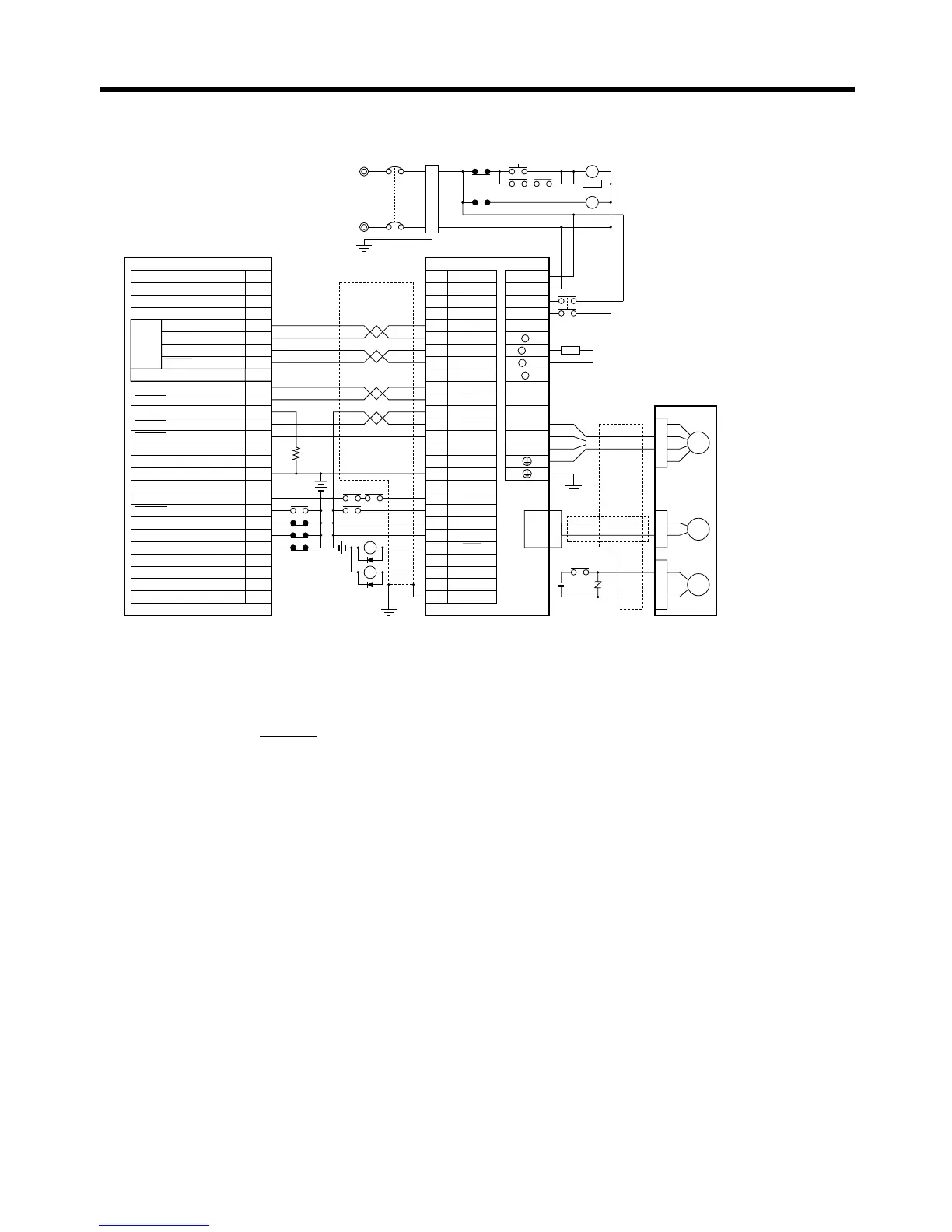
■ Connection Example 12: Connecting to Melec C-870V1
Note 1. Incorrect signal wiring can cause damage to Units and the Servo Driver.
Note 2. Leave unused signal lines open and do not wire them.
Note 3. The diode recommended for surge absorption is the ERB44-02 (Fuji Electric) or equivalent.
Note 4. Do not use the 24-V DC brake power supply for the 24-V DC control power.
Note 5. Do not use XDRST as a general-purpose output.
R7D-AP@
R7M-A@
Contents No.
CN1 TB
XCCWP
XCCWP
XCWP
XCWP
XDRST
XZORG
XZORG
XDEND
EXTV
EXTVGND
XNORG
XCWLM
XCCWLM
FSSTOP
4
1
2
5
6
33
32
8
13
14
18
10
35
34
7
Shell
3 +CCW
L1C
L2C
L1
L2
B1
B2
U
V
W
1
2
−CCW
+CW
−CW
+ECRST
−ECRST
ZCOM
INP
+24VIN
RUN
RESET
OGND
ALMCOM
ALM
FG
Z
19
20
17
18
22
XDRSTCOM 21
29
30
23
14/15
64/65
1
3
2
48
X-axis
pulse
output
CN2
M
E
X1
XB
24 V DC
Red
White
Blue
Green/
Yellow
Noise filter
R
T
Single-phase 200/230 V AC 50/60 Hz
Single-phase 100/115 V AC 50/60 Hz
MC
MC
SUP
NFB
ONOFF
X1
X1MC
Main-circuit power supply
Main-circuit contact
Servo error display
Surge killer
X1
24 V DC
DC reactor
PL
B
24 V DC
XB
BKIR
R88A-CPU@S
2.2 kΩ
Class D ground
(Class 3 ground:
100 Ω or less)
+
+
+
−
Servomotor cable
• Integrated
• Separate
(power and
encoder)
C-870V1 (Melec)

 Loading...


