Chapter 3
3-38
System Design and Installation
Note There is some loss due to winding resistance, so the actual regenerative energy will be approx-
imately 90% of the values derived from these equations.
• For Servo Driver models with internal capacitors for absorbing regenerative energy (i.e., models of
400 W or less.), the values for both Eg1 or Eg2 (unit: J) must be lower than the Servo Driver’s
regenerative energy absorption capacity. (The capacity varies depending on the model. For details,
refer to 3-3-2 Servo Driver Regenerative Energy Absorption Capacity.)
• For Servo Driver models with internal regeneration resistance for absorbing regenerative energy
(i.e., models of 750 W), the average amount of regeneration P
r
(unit: W) must be calculated, and
this value must be lower than the Servo Driver’s regenerative energy absorption capacity. (For
details, refer to 3-3-2 Servo Driver Regenerative Energy Absorption Capacity.)
The average amount of regeneration (P
r
) is the power consumed by regeneration resistance in
one cycle of operation.
P
r
= (E
g1
+ E
g2
)/T [W]
T: Operation cycle [s]
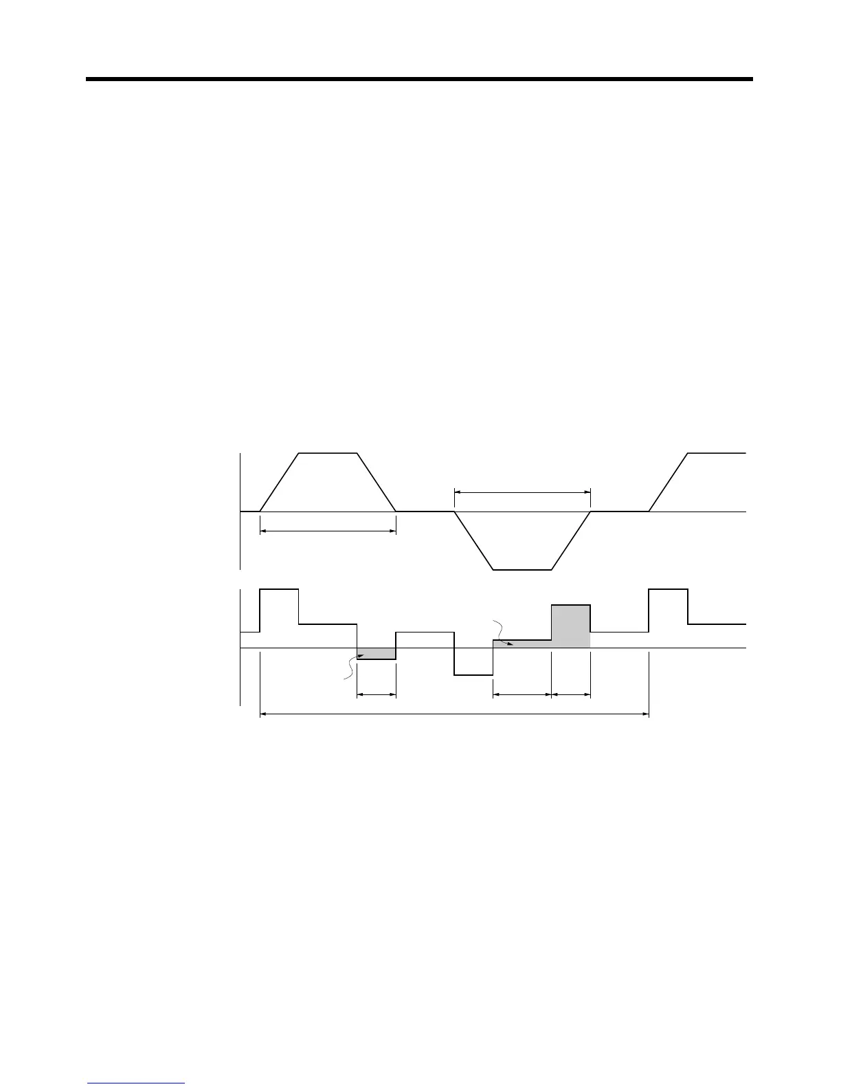
■ Vertical Axis
Note In the output torque graph, acceleration in the positive direction (rise) is shown as positive, and
acceleration in the negative direction (fall) is shown as negative.
• The regenerative energy values for E
g1
, E
g2
, and E
g3
are derived from the following equations.
Fall
Rise
Servomotor operation
Servomotor output torque
+N
1
−N
2
t
1
t
2
t
3
T
E
g1
E
g3
E
g3
T
D2
T
L2
T
D1
E
g2

 Loading...


