Chapter 2
2-22
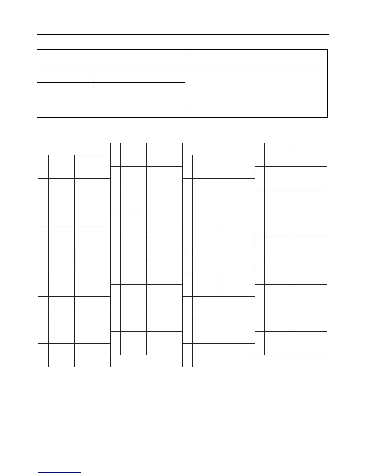
Standard Models and Specifications
● Interface for RS-422
■ CN1: Pin Arrangement
Note Do not wire the empty pins.
● CN1 Connectors (36P)
Servo Driver receptacle 10236-52A2JL (Sumitomo 3M)
Cable solder plug 10136-3000VE (Sumitomo 3M)
Cable case 10336-52A0-008 (Sumitomo 3M)
Pin
No.
Signal name Function Contents
20 RXD+
Reception data Interface for RS-422A transmission and reception.
21 RXD–
22 TXD+
Transmission data
23 TXD–
24 RT
Terminating resistance terminal Connect to pin 21 (RXD–) on the end Unit.
19 GND
RS-422A ground Ground for RS-422A.
2
4
6
8
−PULS
/−CW/−A
10 OGND
12
−SIGN
/−CCW
/−B
14
−ECRST
16
18
1
3
5
7
+PULS
/+CW/+A
9
11
+SIGN
/+CCW/+B
13
15
+ECRST
17
28
RXD+
29
TXD+
33
35
31
ALM
ALMCOM
RUN
− feed pulse,
− reverse pulse,
− phase A
Output ground
common
− direction
signal,
− forward pulse,
− phase B
Deviation
counter reset
+ feed pulse,
+ reverse pulse,
+ phase A
+ direction
signal,
+ forward pulse,
+ phase B
Reception
data +
Transmission
data +
Alarm output
Alarm output
ground
RUN command
input
Z
Encoder
phase-Z
output
20
22
24
26
INP
+ deviation
counter reset
Positioning
completed
output
+24VIN
Control DC
+24-V input
36
RESET
Alarm reset
input
BKIR
Brake interlock
output
RT
Terminating
resistance
terminal
27
19
21
23
25
32
34
30
GND
Ground for
RS-422A
RXD−
TXD−
Transmission
data −
Reception
data −
ZCOM
Phase-Z
output ground

 Loading...


