Chapter 6
6-7
Appendix
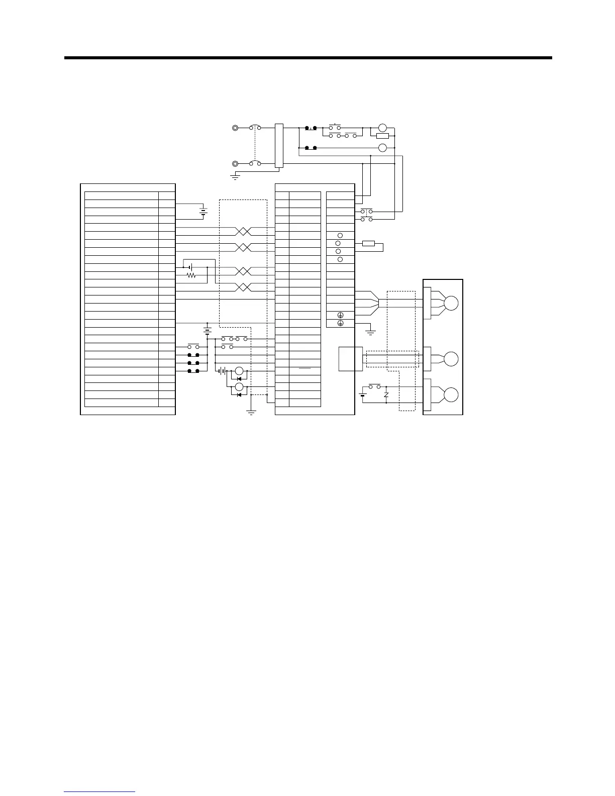
■ Connection Example 6: Connecting to 3F88M-DRT141 Single-axis
Positioner for DeviceNet
Note 1. Incorrect signal wiring can cause damage to Units and the Servo Driver.
Note 2. Leave unused signal lines open and do not wire them.
Note 3. The diode recommended for surge absorption is the ERB44-02 (Fuji Electric) or equivalent.
Note 4. Do not use the 24-V DC brake power supply for the 24-V DC control power.
Note 5. General-purpose I/O is one allocation example. The emergency stop and limit input contacts
are NC and the driver in-position and origin proximity contacts are NO.
3F88M-DRT141 R7D-AP@
R7M-A@
Contents No.
CN1 TB
+24-V power supply
(power supply for Unit)
A24
VDD ground
(power supply for Unit)
CCW pulse (+)
CCW pulse (−)
CW pulse (+)
CW pulse (−)
Power supply for origin 24 V
Deviation counter reset (+)
Deviation counter reset (−)
Origin sensor input
Driver in-position
+24-V power supply (for general input)
Origin proximity
+ Limit input
− Limit input
Emergency stop
B24
4
1
2
5
6
33
32
8
13
14
18
10
35
34
7
Shell
3 +CCW
L1C
L2C
L1
L2
B1
B2
U
V
W
1
2
−CCW
+CW
−CW
+ECRST
−ECRST
ZCOM
INP
+24VIN
RUN
RESET
OGND
ALMCOM
ALM
FG
Z
B21
B22
A21
A22
A11
A20
B20
B11
B10
A1
A10
A9
B9
B2
CN2
M
E
X1
XB
24 V DC
24 V DC
Red
White
Blue
Green/
Yellow
Noise filter
R
T
Single-phase 200/230 V AC 50/60 Hz
Single-phase 100/115 V AC 50/60 Hz
MC
MC
SUP
NFB
ONOFF
X1
X1MC
Main-circuit power supply
Main-circuit contact
Servo error display
Surge killer
X1
24 V DC
DC reactor
PL
B
24 V DC
XB
BKIR
R88A-CPU@S
24 V DC
1.6 kΩ
Class D ground
(Class 3 ground:
100 Ω or less)
+
+
+
−
Servomotor cable
• Integrated
• Separate
(power and
encoder)

 Loading...


