Chapter 4
4-13
Operation
■ Setting the Gain Adjustment Rotary Switch during Online Autotuning
• Setting the gain adjustment rotary switch during online autotuning sets the servo system’s target
speed loop gain and position loop gain.
• Select a switch setting from the following 10 levels (switches A to F are the same setting) to suit the
mechanical system.
Note The servo system loop gain will increase in response to a higher switch setting value, shorten-
ing positioning time. If the setting is too large, however, the machinery may vibrate. Reduce the
setting if vibration is a problem.
4-5-2 Manual Tuning
■ Manually Tuning
• If online autotuning operations are not effective, tune the system using only the gain adjustment
rotary switch.
• When the load inertia fluctuates below 200 ms or less
• When the rotation speed does not exceed 500 r/min, or when the output torque does not ex-
ceed 50% of the rated torque
• When an external force is always imposed, such as with a vertical axis
• When the load rigidity is low, or when the adhesive friction is high
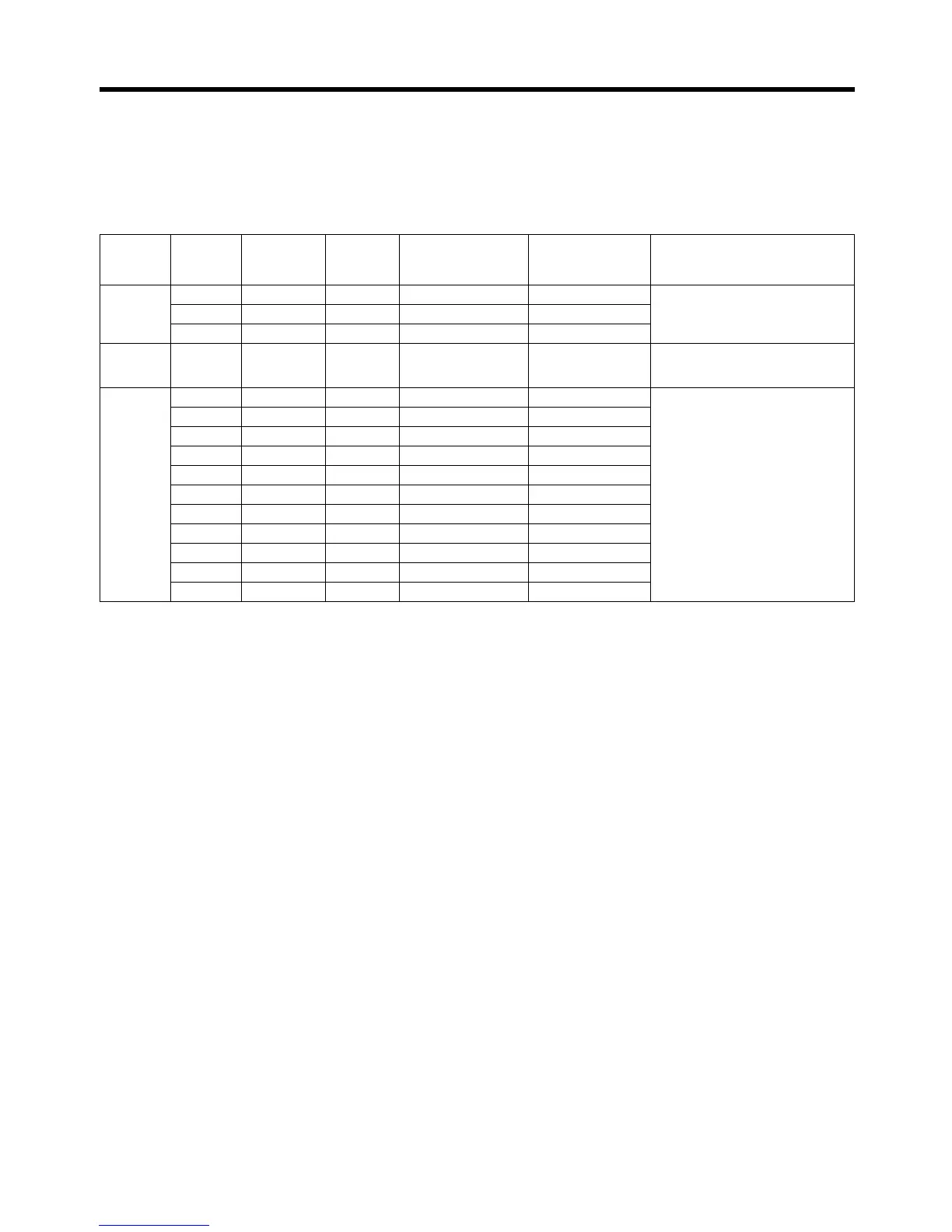
Response Switch
setting
Position
loop gain
(s
–1
)
Speed
loop gain
(Hz)
Speed loop integral
time constant
(
×0.01 ms)
Torque command
filter time constant
(
×0.01 ms)
Typical applications
(mechanical system)
Low 1 15 15 4,000 250 Articulated robots, harmonic drives,
chain drives, belt drives, rack and
pinion drives, etc.
2 20 20 3,500 200
3 30 30 3,000 150
Medium 4 40 40 2,000 100 XY tables, orthogonal robots, gen-
eral-purpose mechanical systems,
etc.
High 5 60 60 1,500 70 Ball screws (direct couplings), feed-
ers, etc.
6 85 85 1,000 50
7 120 120 800 30
8 160 160 600 20
9 200 200 500 15
A 250 250 400 10
B 250 250 400 10
C 250 250 400 10
D 250 250 400 10
E 250 250 400 10
F 250 250 400 10

 Loading...


