Chapter 3
3-17
System Design and Installation
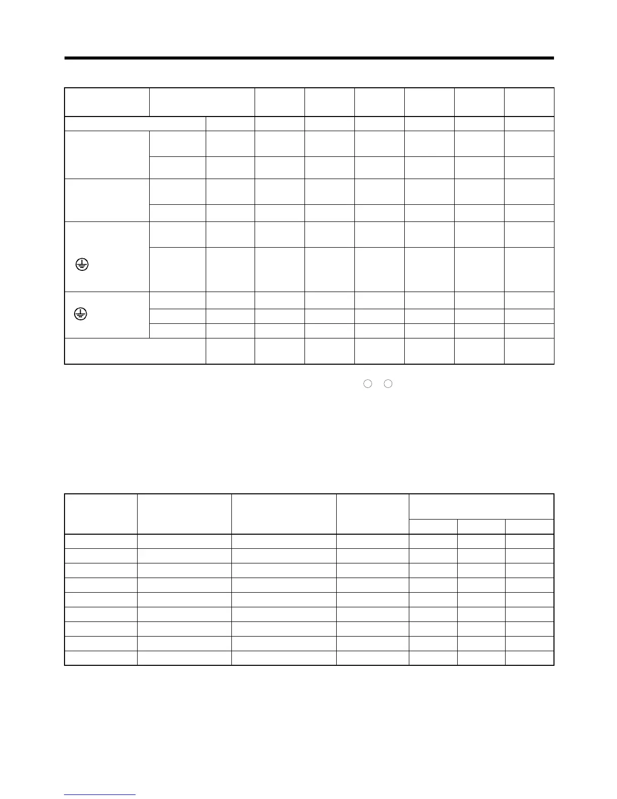
● 200V AC Input (R7D-AP@H)
Note 1. Use the same wire sizes and tightening torques for 1, 2, B1, and B2.
Note 2. Connect an OMRON Servomotor Cable to the Servomotor connection terminals.
■ Wire Sizes and Allowable Current
The following table shows the allowable current for when there are three wires.
● 600-V Heat-resistant Vinyl Wiring (HIV) (Reference Values)
Item Model
Unit
R7D-
APA3H
R7D-
APA5H
R7D-
AP01H
R7D-
AP02H
R7D-
AP04H
R7D-
AP08H
Power supply capacity kVA 0.2 0.25 0.4 0.75 1.2 2.1
Main circuit
power supply
input (L1, L2)
(See note 1.)
Effective
current
A (rms) 0.82 1.1 2.0 3.4 5.5 9.4
Wire size
mm
2
1.25 1.25 1.25 1.25 2 2
Control circuit
power supply
input (L1C, L2C)
Effective
current
A (rms) 0.1 0.1 0.1 0.1 0.1 0.1
Wire size
mm
2
1.25 1.25 1.25 1.25 1.25 1.25
Effective
current
A (rms) 0.42 0.6 0.89 2.0 2.6 4.4
Wire size
mm
2
1.25 1.25 1.25 1.25 1.25 2
Wire size
mm
2
222222
Screw size– M4M4M4M4M4M4
Tor q ue N
⋅m 1.2 1.2 1.2 1.2 1.2 1.2
No-fuse breaker or fuse
capacity
A (rms)4444811
AWG size Nominal cross-
sectional area
(mm
2
)
Configuration
(wires/mm
2
)
Conductive
resistance (
Ω/
km)
Allowable current (A) for
ambient temperature
30
°C40°C50°C
20 0.5 19/0.18 39.5 6.6 5.6 4.5
– 0.75 30/0.18 26.0 8.8 7.0 5.5
18 0.9 37/0.18 24.4 9.0 7.7 6.0
16 1.25 50/0.18 15.6 12.0 11.0 8.5
14 2.0 7/0.6 9.53 23 20 16
12 3.5 7/0.8 5.41 33 29 24
10 5.5 7/1.0 3.47 43 38 31
8 8.0 7/1.2 2.41 55 49 40
6 14.0 7/1.6 1.35 79 70 57
Servomotor
connection ter-
minal (U, V, W,
)
(See note 2.)
Frame ground
( )
+ +

 Loading...


