23180-000 Rev A Mobile Robot LD, LD-CT Assembly Instructions 45
Aux Sensors
Connector type: HDB15M
Use: Low Front Laser, optional vertical lasers
/dev/ttyUSB5 (side lasers)
/dev/ttyUSB6 (side lasers)
/dev/ttyUSB7 (side lasers)
5 V @ 1 A (shared with USB port 1)
5 V @ 1 A (shared with USB port 2)
/dev/ttyUSB5 (side lasers)
/dev/ttyUSB6 (side lasers)
/dev/ttyUSB7 (side lasers)
5 V @ 1 A (shared with USB port 3)
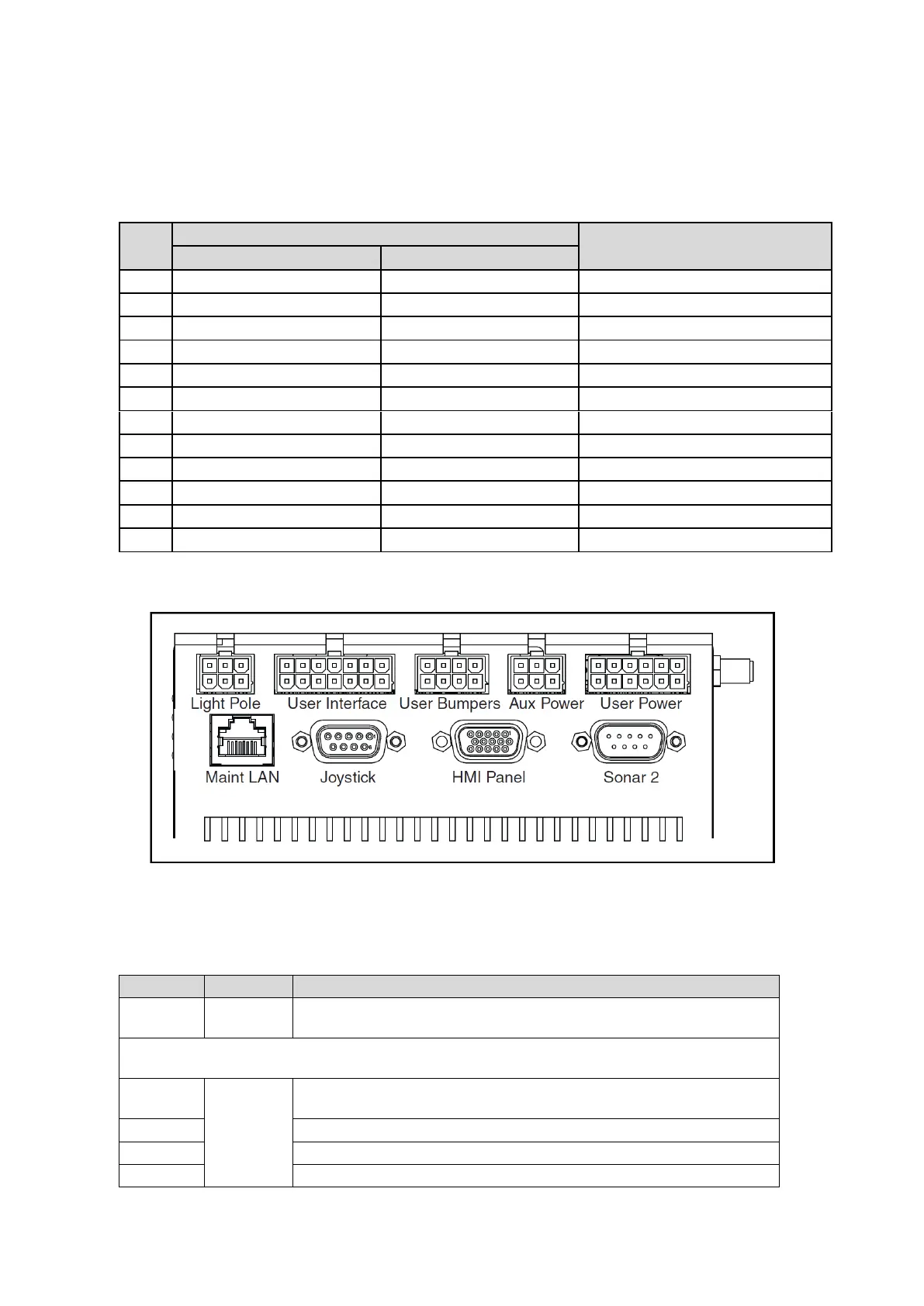
LD Platform Core Rear, Upper
Figure 14: Rear Upper Core
NOTE:
The connectors in the top row of the rear upper core mate with Molex Mini-Fit
Jr™ 5557 series receptacles.
Connects to a user-supplied light tower with 3 lights and 1 buzzer, using a default
configuration
NOTE:
The following four functions are pins on the User Interface connector.
Pins for user-supplied brake release
Pins for user-supplied ON button; same function as Operator Panel ON
Pins for user-supplied OFF button; same function as Operator Panel OFF
Pins for user-supplied E-Stop (must be used or jumpered)
 Loading...


