2 - 5
2 Configuration Units
NA-series Programmable Terminal Hardware(-V1) User’s Manual (V125)
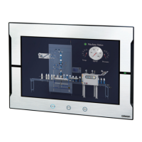
2-1 NA Units
2
2-1-1 Components and Functions
Confirm the safety of the system before turning ON or OFF the power supply, or pressing the
reset switch.
Battery
The following Battery is provided as a standard feature.
Power Supply Connector Pin Arrangement
No. Name Description
(a) Battery cover Open this cover to replace the Battery.
(b) ID information label You can check the ID information of the NA Unit.
(c) SD Memory Card connector Insert an SD Memory Card here.
(d) Protective ground terminal Use for protective grounding.
(e) Ethernet port 1 Connect a device other than the Sysmac Studio.
Ethernet port 2 Connect mainly the Sysmac Studio.
(f)
Serial port
*1
*1. The serial port is for future expansion.
For future expansion.
(g) USB host port Connect this port to a USB Memory Device, keyboard, mouse, etc.
(h) USB slave port Connect the Sysmac Studio or other devices.
(i) Reset switch Use this switch to reset the NA Unit.
(j) DC input terminals These are the power supply terminals. Connect the accessory power
supply connector and supply power.
(k) Battery connector Connect the connector on the backup Battery here.
(l) DIP switch Used for system recovery. (The DIP switch is on a PCB that is accessed
by opening the Battery cover.) In other cases, do not change any of the
factory settings of the pins on the DIP switch.
(m) Battery This is the battery to backup the clock information in the NA Unit.
Model Appearance Specifications
CJ1W-BAT01 Effective life (i.e., maximum life expectancy): 5 years
The following data is retained during power interruptions.
• Time data
Pin No. Signal name
Name
1 +24 V +24-V input
20 V 0 V
3 FG Functional ground
 Loading...