EasyManua.ls Logo

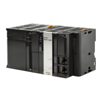
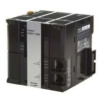
Omron NJ301-1100 User Manual

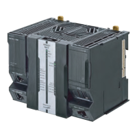
Omron NJ301-1100
400 pages
To Next Page IconTo Next Page
Page #1 background imageLoading...
Page #1 background image
Machine Automation Controller
NJ-series
CPU Unit
Hardware
CPU Unit
Power Supply Unit
Basic I/O Units
User’s Manual
W500-E1-17
NJ501-
NJ301-1
NJ101-
NJ-P3001
CJ1W-ID/IA
CJ1W-INT01
CJ1W-IDP01
CJ1W-OC/OD/OA
CJ1W-MD
CJ1W-B7A

Table of Contents

Other manuals for Omron NJ301-1100

Questions and Answers:

Omron NJ301-1100 Specifications

General IconGeneral
ModelNJ301-1100
Cycle Time1 ms
Ethernet Ports2
Built-in EtherNet/IP PortYes
EtherNet/IPYes
Built-in EtherCAT PortYes
SD Memory Card SlotYes
Power Supply24 VDC
Operating Temperature0 to 55 °C
Data Memory Capacity128 KB
EtherCAT Refresh Cycle1 ms
Programming LanguageIEC 61131-3 (LD, ST, FBD, SFC, IL)
Weight1.5 kg
I/O pointsUp to 256

Summary

Machine Automation Controller

Introduction

Sections in this Manual

4 Installation and Wiring

Explains how to install and wire the CPU Unit and configuration units.

5 Troubleshooting

Covers error identification, troubleshooting flowcharts, and hardware errors.

6 Inspection and Maintenance

Details required inspections and maintenance procedures.

Safety Precautions

Precautions for Safe Use

Guidelines for safe product usage.

Precautions for Correct Use

Guidelines for proper product operation and performance.

Precautions for Safe Use

Precautions for Correct Use

Regulations and Standards

Versions

1 Introduction to NJ-series Controllers

1-2 Specifications

Detailed specifications of the NJ-series Controllers.

2 System Configuration

3 Configuration Units

3-1 CPU Units

Information on NJ-series CPU Units, including models and specifications.

3-3 Power Supply Units

Specifications and selection guide for NJ-series Power Supply Units.

3-4 CJ-series Basic I/O Units

Specifications for CJ-series Basic I/O Units.

4 Installation and Wiring

4-1 Processing at Power ON and Power OFF

Describes processing during power ON and OFF states.

4-2 Fail-safe Circuits

Provides guidance on implementing fail-safe circuits.

4-3 Mounting Units

Instructions for mounting various units and racks.

4-4 Wiring

Detailed wiring instructions for various components.

4-5 Control Panel Installation

Guidelines for installing the system within a control panel.

5 Troubleshooting

5-1 Operation after an Error

Describes controller status and operation after an error.

5-2 Troubleshooting

Provides error identification and troubleshooting flowcharts.

6 Inspection and Maintenance

6-1 Periodic Maintenance and Inspection

Details required inspections for maintaining peak performance.

A Appendices

Related product manuals