2-2 Part Names and Functions
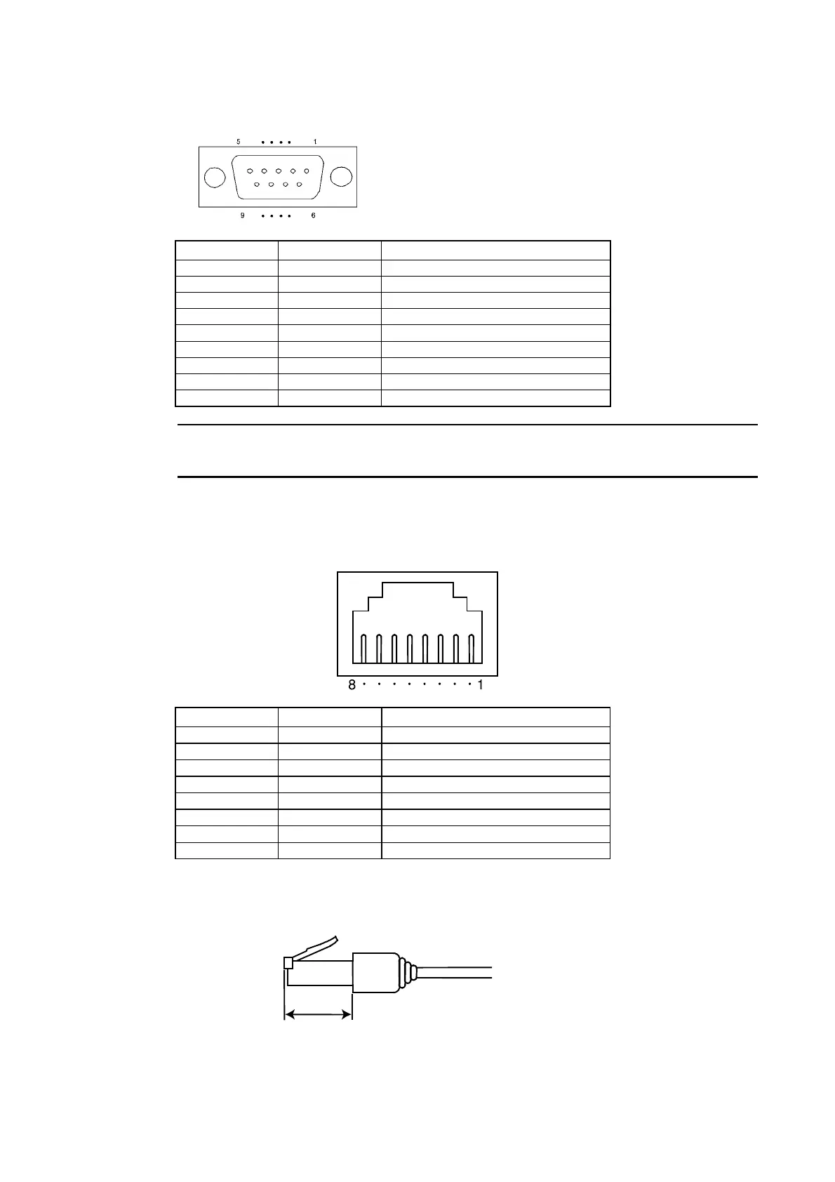
Connector Pin Arrangement of Serial Ports A and B
Pin number Signal name Name
1 NC Not connected.
2 SD Send data
3 RD Receive data
4 RS Request to send
5 CS Clear to send
6 +5V 5-V output (250 mA max.)
7 NC Not connected.
8 NC Not connected.
9 SG Signal ground
Note
Make sure that the total current capacity of devices being supplied power is 250 mA max. be-
fore using the 5-V power supply from pin 6. The capacity of the PT's 5-V output is 250 mA
max. at 5 V ±5%.
Ethernet Connector Pin Arrangement
Pin number Signal name Name
1 TD+ Twisted-pair output (differential output)
2 TD− Twisted-pair output (differential output)
3 RD+ Twisted-pair input (differential input)
4 BI_D+ Protection circuit
5 BI_D− Protection circuit
6 RD− Twisted-pair input (differential input)
7 BI_D+ Protection circuit
8 BI_D− Protection circuit
When using a cable with a hood (or boot), make sure that the length for connection is at least
15 mm, as shown in the following diagram.
15 mm min.
2-14

 Loading...


