3-8 Installing the Controller Link Interface Unit
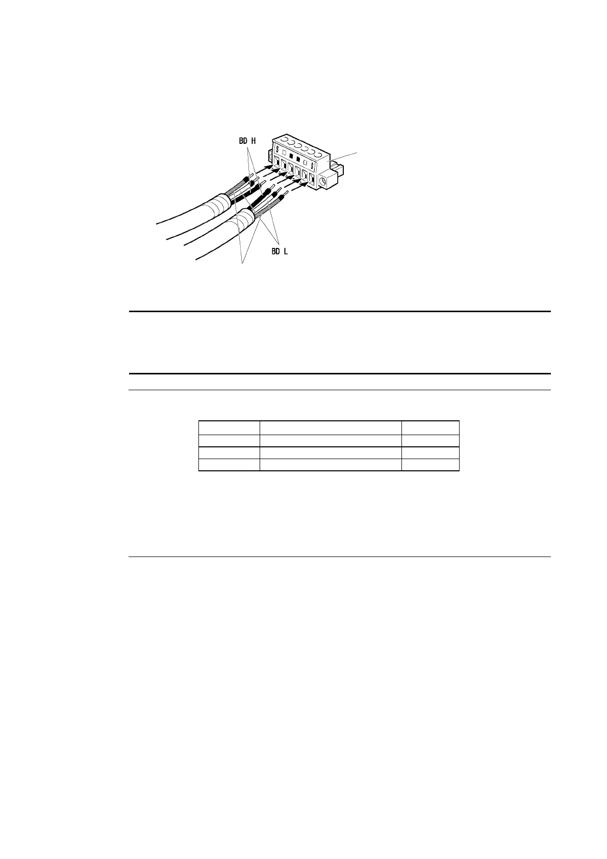
6. Carefully insert the signal and shield lines into the respective holes of the connector
(identified with the markings). Ensure that the connector is oriented correctly. The f
ing example is for connection to a Board in the middle of the network.
ollow-
Cable connecto
Shield lines
Note • Loosen the screws in the connector enough to allow the terminal to pass before inserting
the signal line. If the screw is not loosened, the signal line will go completely into the con-
nector and you will not be able to secure the line.
• Attach crimp terminals to the wires. Never connect bare power supply wires directly to the
connector.
Reference • Marks are provided on the connector for the signal lines. Connect the signal lines ac-
cording to the marks.
Marking Signal name Line color
BD H (communications data high) Black
BD L (communication data low) White
S SHLD (shield) −
• Marks indicate signals as listed above.
• The lines can be connected to either the right or left half of the connector at the node
on either end of the network.
• If grounding by node, the connection method for the shield is different.
Refer to Wiring Communications Cable and Connecting the Shield Line to the Con-
nector under 3-8-4 Wiring, for details on connecting the shield to the connector.
7. Firmly secure each signal line with the signal line screws in the connector. An ordinary
flat-blade screwdriver with a tip that tapers at the end is not suitable because it cannot be
inserted far enough. Use a small flat-blade screwdriver with a uniform width. The applica-
ble tightening torque is 0.2 N
⋅m.
3-53

 Loading...


