5-1 Connecting to Host Via Ethernet
CS1W-ETN11
CS1W-ETN21
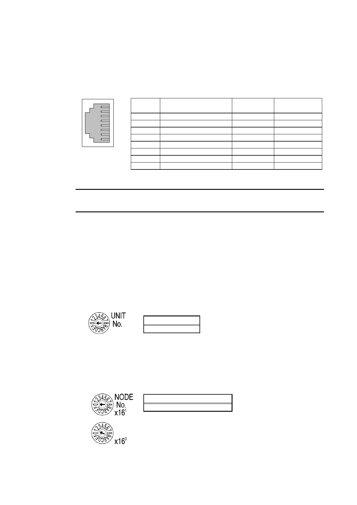
This is the connector used to connect the twisted-pair cable to the Ethernet.
•
•
Electrical characteristics: Conforms to IEEE802.3 standards.
Connector structure: RJ45 8-pin modular connector (conforms to ISO8877).
Connec-
tor Pin
Signal name Abbreviation Signal direction
1 Send data + TD+ Output
2 Send data − TD− Output
3 Receive data + RD+ Input
4 Not used. − −
5 Not used. − −
6 Receive data − RD- Input
7 Not used. − −
8 Not used. − −
1
8
• CJ-series PLCs
Note
• Always turn OFF the power to the PLC before setting the rotary switches.
• Create I/O tables for the CPU Unit when setting the unit number for the first time or c
ing settings.
hang-
CJ-series Ethernet Units:
CJ1W-ETN11
CS1W-ETN21
Setting the Front Panel Switches
Setting Unit Numbers
Always set the unit numbers so that the unit numbers of other CPU Bus Units mounted to the
same CPU Unit are all unique.
Use a small screwdriver to set the rotary switches, being careful not to damage them.
The factory setting is 0.
Setting range
0 to F
Setting Node Numbers
Set the node numbers as hexadecimal values with the node number setting switch. Always
set the node numbers so that other Ethernet Units connected to the same Ethernet network
all have unique addresses. As long as the addresses are unique, they can be set between 01
and 7E (1 to 126 decimal).
Setting range
01 to 7E (1 to 126 decimal)
5-11
 Loading...


