Do you have a question about the Omron NS8-TV10 V1 Series and is the answer not in the manual?
Describes the role and functions of NS-series PTs for new users.
Explains how NS-series PTs allow word and bit allocation for PLC access and communication.
Outlines the procedure for starting up an NS-series system, covering host and PT connections.
Details the networks for hosts that can be used with NS-series PTs.
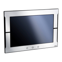
Describes the part names and functions of the PT, including front and rear panels.
Covers installation procedures, including environment, mounting, and power connections.
Details the procedure for starting the PT and its operation at startup.
Explains how to connect the PT to a computer using RS-232C, Ethernet, or USB.
Describes how to connect and set up bar code readers with the PT.
Explains how to use memory cards for data storage and transfer.
Details methods for connecting the host to serial port A or B using RS-232C or RS-422A.
Explains connecting multiple PTs to a single host in a 1:N configuration.
Describes connecting to high-speed 1:N NT Links using RS-232C or RS-422A.
Details network connection setup using Ethernet, including required devices and host settings.
Explains connecting to the host using a Controller Link Interface Unit and data links.
Explains PT operating modes and the configuration of the System Menu.
Details functions for initializing, saving data, and removing memory cards.
Covers settings for startup wait time, screen saver, sounds, backlight, and printer.
Describes setting password functions, including levels, timeouts, and screen switching.
Details setting communications conditions for serial ports, Ethernet, and Controller Link.
Covers displaying data histories, device monitor, comms test, and version information.
Explains how to perform hardware checks for LCD and touch switch functionality.
Details how to switch to RUN mode, start operations, and check communications.
Covers maintaining the PT in optimum condition, including backing up data and spare units.
Provides a table of symptoms, causes, and measures for errors during data transfer, PT startup, and operation.
Shows wiring layouts for connecting PT to host via RS-232C and RS-422A.
| Display Size | 8.4 inches |
|---|---|
| Display Type | TFT LCD |
| Resolution | 800 x 600 pixels |
| Touch Type | Analog Resistive |
| Supply Voltage | 24 V DC |
| Protection | IP65 (front panel) |
| Brightness | 400 cd/m² |
| Backlight Life | 50, 000 hours |
| Operating Temperature | 0 to 50 °C |
| Storage Temperature | -20 to 60 °C |
| Weight | 1.5 kg |
| Communication Ports | Ethernet, USB, RS-232C, RS-422/485 |
| Humidity | 10 to 90% (non-condensing) |
| Vibration Resistance | 10 to 57 Hz, amplitude 0.075 mm; 57 to 150 Hz, 9.8 m/s² (1 G) |
| Shock Resistance | 147 m/s² (15 G), 3 times in each of 3 axes |