2-2 Part Names and Functions
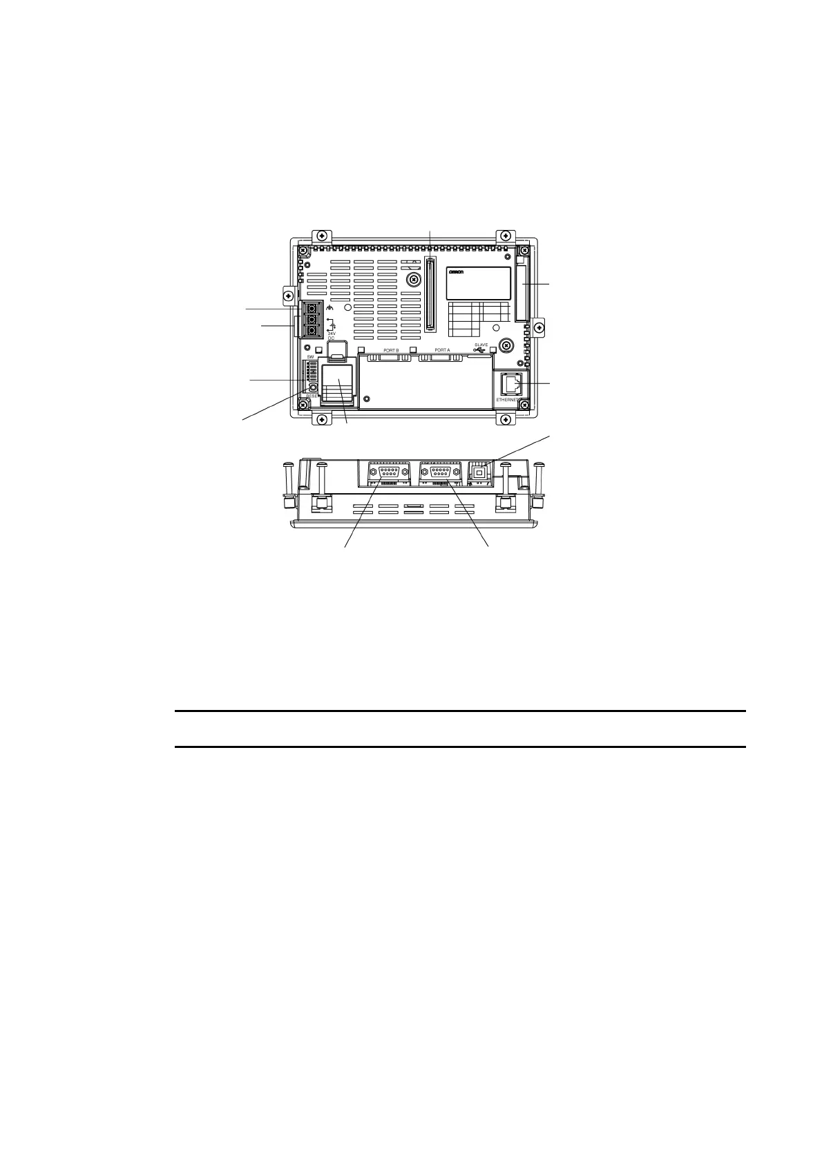
NS5 Rear Panel
Local Bus Interface Connector
Used to connect to an Expansion Interface Unit.
(Applicable with NS Ver. 6 or higher systems.) Current
Expansion Interface Units (NS-CA001, NS-CA002, and
NCCKL21) cannot be connected.
Ethernet Connector
Used to connect the Ethernet cable.
Uses a 10Base-T/100Base-T 8-pin
modular plug.
USB Slave Connector
This is a USB Type B connector.
Refer to 3-3-2 Connecting via
USB.
FG Terminal
Used to prevent malfunctions
due to noise interference.
Main Circuit DC Input Terminals
Used to connect the power supply.
Reset Switch
Used to initialize the PT. The status
of screen data, other registered data,
and the system menu, however, will
not change.
DIP Switch
Used to set the settings for
transmitting data using the
Memory Card.
Battery Cover
The battery is installed
underneath the cover.
Serial Port B Connector
Used to connect the host, CX-
Designer, and Bar Code Reader.
Uses an RS-232C 9-pin connector.
Serial Port A Connector
Used to connect the host, CX-
Designer, and Bar Code Reader.
Uses an RS-232C 9-pin connector.
USB Slave Connector
This is a USB Type B connector.
Refer to 3-3-2 Connecting via
USB.
Note
Confirm system safety before turning the power ON/OFF or restarting. Otherwise the system
may operate unpredictably.
2-12
 Loading...