3-8 Installing the Controller Link Interface Unit
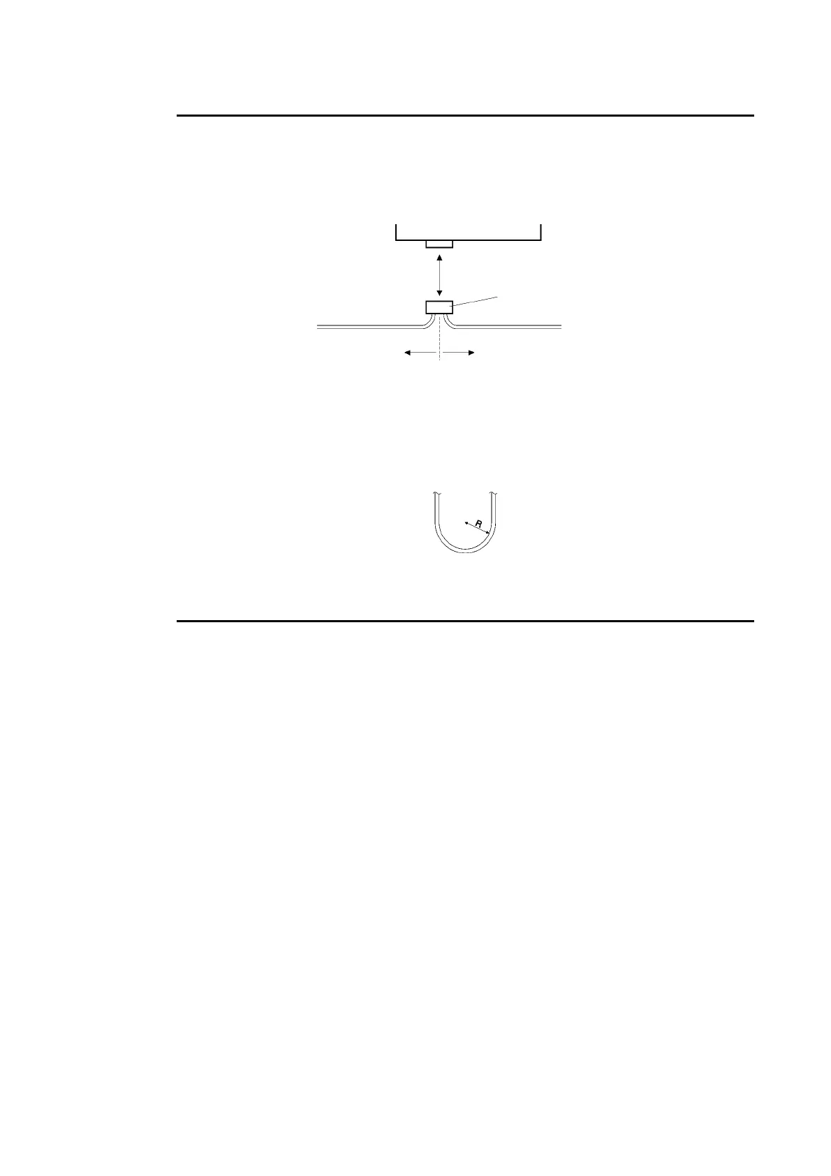
Note • If the connector becomes disconnected, not only will the Board be unable to perform com-
munications with other nodes in the network, the network will be split into two at the point of
disconnection. Take the utmost care to ensure that the connector does not become discon-
nected during communications.
Controller Link Support Board
Communications disabled
Connector
Network split
(communications disabled)
• Do not pull on the communications cable.
• When bending the communications cable, allow 60 mm or more for the bending radius (R).
• Do not place heavy objects on the communications cable.
• Supply power only after checking the wiring thoroughly.
• Always tighten the screws of connector after connecting the communications cable.
3-55
 Loading...