5-2SectionConnecting to the Host’s RS-232C Port
100
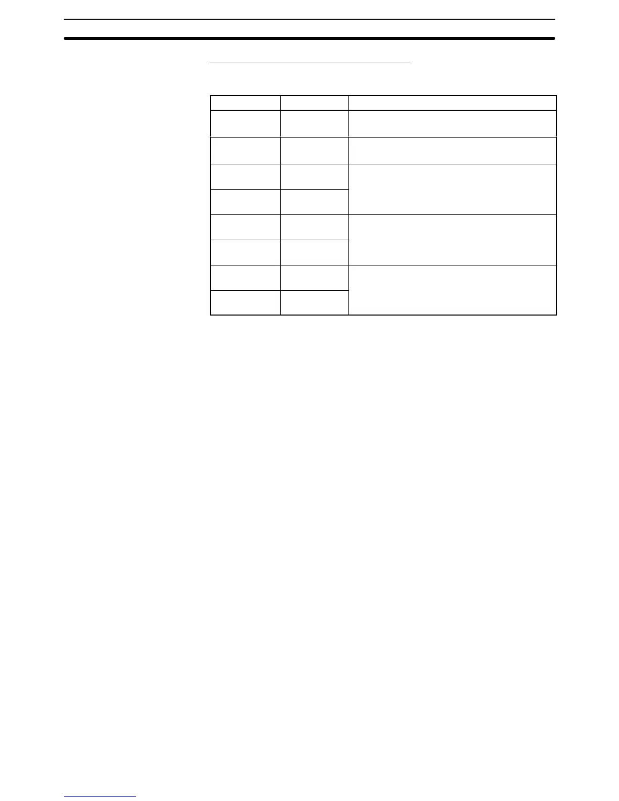
Cables with Connectors Made by OMRON
When
connecting an NT
-AL001 and a PC, use the OMRON cables with connec
-
tors indicated in the table below.
Model Cable Length Connector Specification
XW2Z-200S 2 m
9-pin
⇔
25-pin
Host Link, 1:1 NT Link
XW2Z-200T 2 m
9-pin
⇔
9-pin
Host Link, 1:1 NT Link
SJ45007-102
1 m
9-pin
⇔
9-pin
Host Link, 1:1 NT Link
SJ45007-202
2 m
+5 V power supply wire attached
(Use when the PC does not have a +5 V output.)
XW2Z-070T-1
0.7 m 9-pin
⇔
9-pin
Host Link, 1:1 NT Link, 1:N NT Link
XW2Z-200T-1
2 m
+5 V power supplied from PC
(Use when the PC has a +5 V output.)
SJ46006-102
1 m
9-pin
⇔
9-pin
Host Link, 1:1 NT Link, 1:N NT Link
SJ46006-202
2 m
+5 V power supplied from PC
(Use when the PC has a +5 V output.)
Note 1. The maximum tensile load of the recommended cable is 30 N. Do not ex-
ceed this load.
2. After
connecting a connecting cable, always tighten the connector screws.

 Loading...


