7
5
3
1
8
6
4
2
3-2SectionConnecting Link Adapters
26
When using Host Link or 1:1 NT Link communications, set the RS-422A send
mode to “no RS/CS control” by turn OFF both SW1-5 and SW1-6.
When using 1:N NT Link communications (standard or high-speed), set the
communications mode to “RS/CS control” by turning ON either pin SW1-5 or
SW1-6.
Note 1. Do
not turn ON both SW1-5 and SW1-6 at the
same time. This may damage
internal circuits.
2. The
power supply to the device supplying +5 V must be
turned OFF before
starting wiring work.
3. Before connecting the RS-232C cable and turning ON the power to an
RS-232C
device such as a PT
(i.e., turning ON the power to the Link Adapt
-
er),
check that the cable is wired correctly and that the DIP switch
settings
are
correct. If the power is turned ON and there is a wiring fault, the internal
circuits of the Link Adapter or the RS-232C device may be damaged.
4. When
the Link Adapter is connected to a C200HX/HG/HE (-ZE), CQM1H,
CS1G/H,
CS1G/H-H, or CJ1G model of OMRON PC as
an RS-422A device,
set pins SW1-5 and SW1-6 as indicated below.
56
SW1-5
OFF
SW1-6
ON
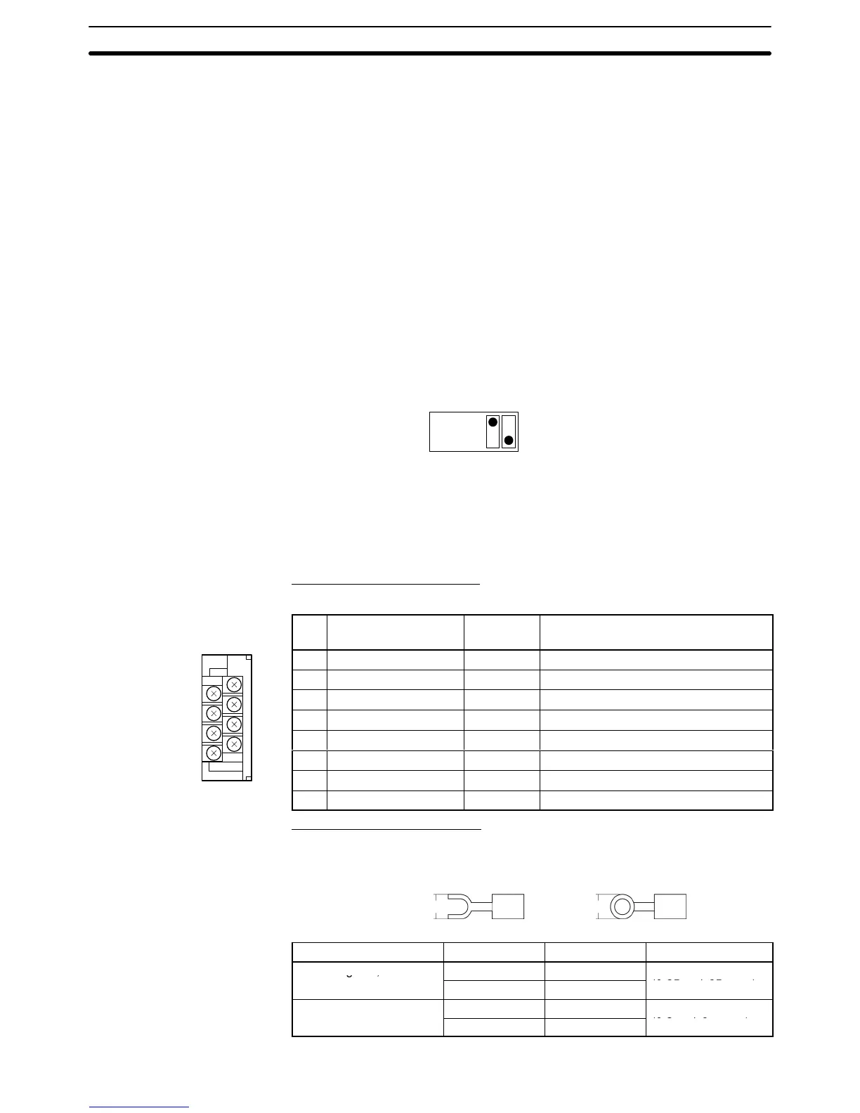
The NT-AL001-E Link Adapter has a terminal block for an RS-422A/485 inter-
face connection and a connector for an RS-232C interface connection.
The
pin allocations for the
RS-422A/485 terminal block and the RS-232C con
-
nector are as follows.
RS-422A/485 Terminal Block
The CSB and CSA signals are for specialized applications.
Pin Signal name Code
Signal direction
(Link Adapter ⇔ Device)
8 Request to send (–) CSA Link Adapter → RS-422A/485 Device
7 Request to send (+) CSB Link Adapter → RS-422A/485 Device
6 Receive data (–) RDA Link Adapter ← RS-422A/485 Device
5 Receive data (+) RDB Link Adapter ← RS-422A/485 Device
4 Send data (–) SDA Link Adapter → RS-422A/485 Device
3 Send data (+) SDB Link Adapter → RS-422A/485 Device
2 Signal ground SG (GND) ---
1 Functional ground ---
Compatible Crimp Terminals
Use crimp terminals for M3 screws.
Fork
terminal
6.2 mm max.
Round terminal
6.2 mm max.
Manufacturer Style Model Compatible wire
J.S.T. Mfg Co., Ltd.
Fork V1.25-N3A
AWG22 to AWG16

 Loading...


