4-1SectionConnecting to the RS-232C Port at the Host
44
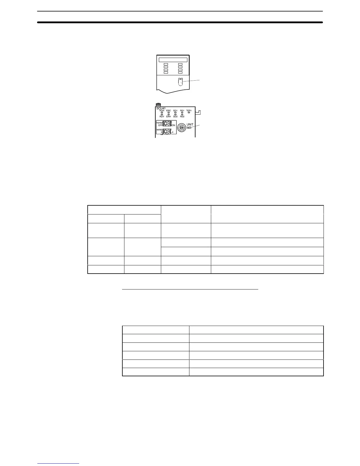
located
on the front panel. Set each switch with a flat blade screwdriver so
that
the values or symbols in the setting value window agree with the following.
Set
the unit number to 0 through F so
that it will not duplicate the numbers
used in other Units.
SCU21
RUN
ERC
SD1
RD1
RDY
ERH
SD2
RD2
UNIT
No.
F
E
C
1
0
CS1W-SCU21
CJ1W-SCU41
Set the unit number to 0 through F so
that it will not duplicate the numbers
used in other Units.
Allocation DM Area Settings for CPU Unit
Settings
are written from the Programming Device (a Programming Console or
CX-Programmer) directly into the allocated DM Area (PC Setup) of the CPU
Unit.
After the settings are written, they become ef
fective by turning the power
ON, restarting the Unit, restarting the communication port, or execution of the
STUP instruction.
The
following table shows the words allocated in the DM Area and the settings.
m = DM30000 + 100 × unit number
Allocated DM word
ngs
m m+10 8000
Host Link mode, 2 stop bits, even parity
, data
length 7 bits
0000 Baud rate 9,600 bps.
m+
0007 Baud rate 19,200 bps.
m+2 m+12 0000 Transmit delay time 0 ms.
m+3 m+13 0000 No CTS control Unit No.0 for Host Link
Connecting to a CPU Unit
CV-series and CVM1/CV-series (-EV
j) CPU Units
CVM1-CPU01-EV2/CVM1-CPU11-EV2/CVM1-CPU21-EV2
PC Setup
When
connecting to a CVM1/CV
-series CPU Unit, set the following communica
-
tion conditions for the PC Setup.
Item Setting at Host
Baud rate Set the same baud rate as set at the NT21
(*1)
Stop bits 2 stop bits
Parity Even
Data length ASCII 7 bits
Unit # 00
*1 Set the Host Link baud rate at 9,600 bps or 19,200 bps with the memory
switch at the NT21. For details, refer to Setting the Host Link Method (page
127).
Either
set PC Setup directly from a Programming Device (e.g., SYSMAC
Sup
-
port
Software), or transmit the PC Setup made at a Programming Device to the
CPU Unit.
For
details on the PC Setup, refer to the
SYSMAC CVM1/CV500/1000/2000 Op
-
eration Manual: Ladder Diagrams (W202-E1-j).

 Loading...


