5-1SectionConnecting to the Host’s RS-422A/485 Port
73
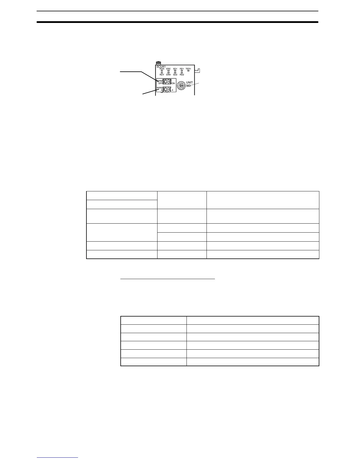
the communications mode switch to select 4-wire (RS-422A) communications
and turn ON the terminator switch to enable the terminating resistance.
Unit
number switch
Set the unit number between 0 and F
so that it will not duplicate the
numbers used in other Units.
T
erminator switch
T
urn ON to connect the terminator
.
(Set terminator ON.)
Communications mode switch
Set the 2-wire/4-wire selector switch to
“4” to select 4-wire (RS-422A)
communications.
Allocation DM Area Settings for CPU Unit
Settings
are written from the Programming Device (a Programming Console or
CX-Programmer) directly into the allocated DM Area (PC Setup) of the CPU
Unit.
After the settings are written, they become ef
fective by turning the power
ON, restarting the Unit, restarting the communication port, or execution of the
STUP instruction.
The
following table shows the words allocated in the DM Area and the settings.
m = DM30000 + 100 × unit number
Allocated DM word
0007 Baud rate 19,200 bps.
m+2 0000 Transmit delay time 0 ms.
m+3 0000 No CTS control Unit No.0 for Host Link
Connecting to a CPU Unit
CVM1/CV-series (-EVj) CPU Units
CVM1-CPU01-EV2/CVM1-CPU11-EV2/CVM1-CPU21-EV2
PC Setup
When
connecting to a CVM1/CV
-series CPU Unit, set the following communica
-
tion conditions for the PC Setup.
Item Setting at Host
Baud rate Set the same baud rate as for the NT21.
(*1)
Stop bits 2 stop bits
Parity Even
Data length ASCII 7 bits
Unit # 00
*1 Set the Host Link baud rate at 9,600 bps or 19,200 bps with the Comm. Speed
memory switch at the NT21. For details, refer to Setting the Host Link Method
(page 125).
Set
the PC
Setup directly from a Programming Device (e.g., SYSMAC Support
Software).
For details on the PC Setup, refer to the SYSMAC CVM1/CV500/CV1000/
CV2000 Operation Manual: Ladder Diagrams (W202-E1-j).

 Loading...


