5-1SectionConnecting to the Host’s RS-422A/485 Port
84
Unit.
After the settings are written, they become ef
fective by turning the power
ON, restarting the Unit, restarting the communication port, or execution of the
STUP instruction.
In
the following table, the relevant word addresses allocated in the DM Area and
settings are shown.
Allocated DM word
Writing
ngs
DM32000 8200 1:N NT Link mode
DM32001 000A Communications baud rate (high-speed)
DM32006 000j
j = The largest model number of the
connected PTs (0 to 7)
For
example, when connecting PT
s with model
numbers 3, 4, 5, and 6 to port 1,
set
DM 32000 to 8200
Hex, DM 32001 to 000A Hex, and DM 32006 to 0006 Hex.
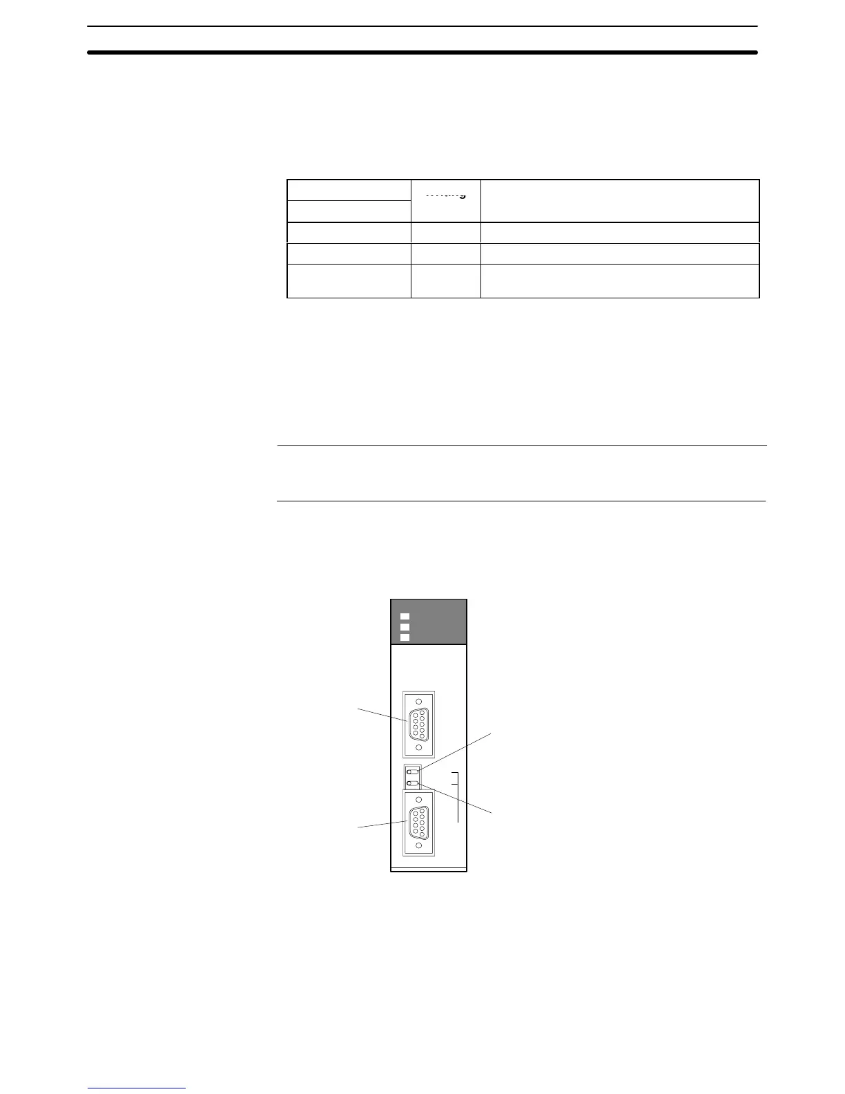
Connecting to a CS-series Serial Communications Board
Serial Communications Board equipped with an RS-422A/485 port for CS-se-
ries CPU Units:
CS1W-SCB41 (Port 2 is an RS-422A/485 port.)
Reference: Serial
Communications Boards and Serial Communications Units with lot num
-
ber
991220
(12/20/99) and later support the high-speed 1:N NT Link. Boards and
Units with earlier lot numbers cannot be used.
Setting the Front Switches
Port
1
RS-232C
Port 2
RS-422A/485
PORT1
ON
TERM
4 WIRE
OFF
2
PORT2
(RS422/
RS485)
RDY
COMM1
COMM2
SCB41
Terminator Switch (TERM)
Set to ON (right side)
Wire Selection Switch (WIRE)
RS-422A:
Set to 4 (right side) for 4-wire.
RS-485:
Set to 2 (left side) for 2-wire.
CPU Unit Allocated DM Area Settings
Setting
is written from the Programming Device
(a Programming Console or CX-
Programmer)
directly into the
allocated DM Area settings (PC Setup) of the CPU
Unit.
After the setting is written, it becomes ef
fective by turning the power ON,
restarting
the Unit, restarting the communication port,
or execution of the STUP
instruction.

 Loading...


