5-1SectionConnecting to the Host’s RS-422A/485 Port
86
When
an NT
-AL001 Link Adapter is being used, the RS-232C cable can be con
-
nected to either serial port A or B on the NT21.
When
an NS-AL002 Link Adapter is being used, the Link Adapter connects di
-
rectly to serial port B on the NT21, so an RS-232C cable is not required.
Connecting the Link Adapter to the Host (RS-422A)
NT21
RS-422A
(500
m max.)
Host
Link Adapter
(NT-AL001 or
NS-AL002)
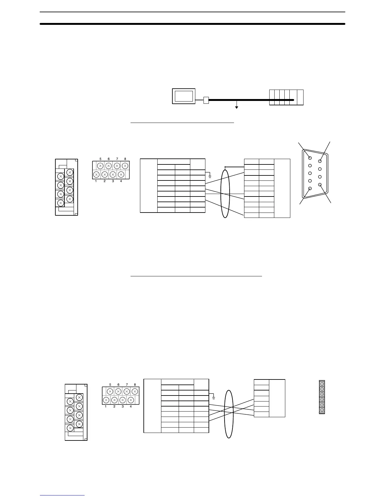
Wiring to a C-series Host Link Unit
Applicable Unit: C200H-LK202-V1
6
5
9
1
NS-AL002
NT-AL001
Shield
Pin number Abbreviation
F. Ground
SG
SDB
SDA
RDB
RDA
CSB
CSA
DIP Switch Settings
NT-AL001: Pins 1 and 2 ON
Pins 3 to 6 OFF
NS-AL002: Pin 4 ON
Pins 1 to 3 OFF
Link Adapter
PC (CPU Unit)
RS-422A
connector
Pin number
Connector
hood
1
2
3
4
5
6
7
8
9
Abbreviation
FG
RDB
–
SG
–
SDB
RDA
FG
–
SDA
(9-pin
type)
RS-422A
terminal
block
NT-AL001
1
2
3
4
5
6
7
8
NS-AL002
1
---
3
7
2
6
---
---
7
5
3
1
8
6
4
2
Note T
o avoid an FG ground loop, do not connect the Link Adapter
’
s functional ground
to the shield wire of the RS-422A cable.
Wiring to a CPM1, CPM2A, CPM2C, or SRM1
Applicable Units:
CPM1-10CDR-j CPM1-20CDR-j
CPM1-30CDR-j
CPM1A-10CDj-j CPM1A-20CDj-j
CPM1A-30CDj-j CPM1A-40CDj-j
CPM2A-30CDjj-j CPM2A-40CDjj-j
CPM2A-60CDjj-j
CPM2C-10jjjjjj-j CPM2C-20jjjjjj-j
SRM1-C02-V2
Connect to the PC through a CPM1-CIF11 RS-422A Adapter.
Shield
Pin number Abbreviation
F. Ground
SG
SDB
SDA
RDB
RDA
CSB
CSA
DIP Switch Settings
NT-AL001: Pins 1 and 2 ON
Pins 3 to 6 OFF
NS-AL002: Pin 4 ON
Pins 1 to 3 OFF
Link Adapter
PC (RS-422A Adapter)
RS-422A
terminal
block
NT-AL001
1
2
3
4
5
6
7
8
NS-AL002
1
---
3
7
2
6
---
---
FG
SG
SDB
SDA
RDB
RDA
RS-422A
terminal
block
Abbreviation
FG
SG
SDB (+)
SDA (–)
RDB (+)
RDA (–)
(9-pin
type)
NS-AL002
NT-AL001
7
5
3
1
8
6
4
2

 Loading...


