6 Incremental Encoder Input Units
6 - 60
NX-series Position Interface Units User’s Manual (W524)
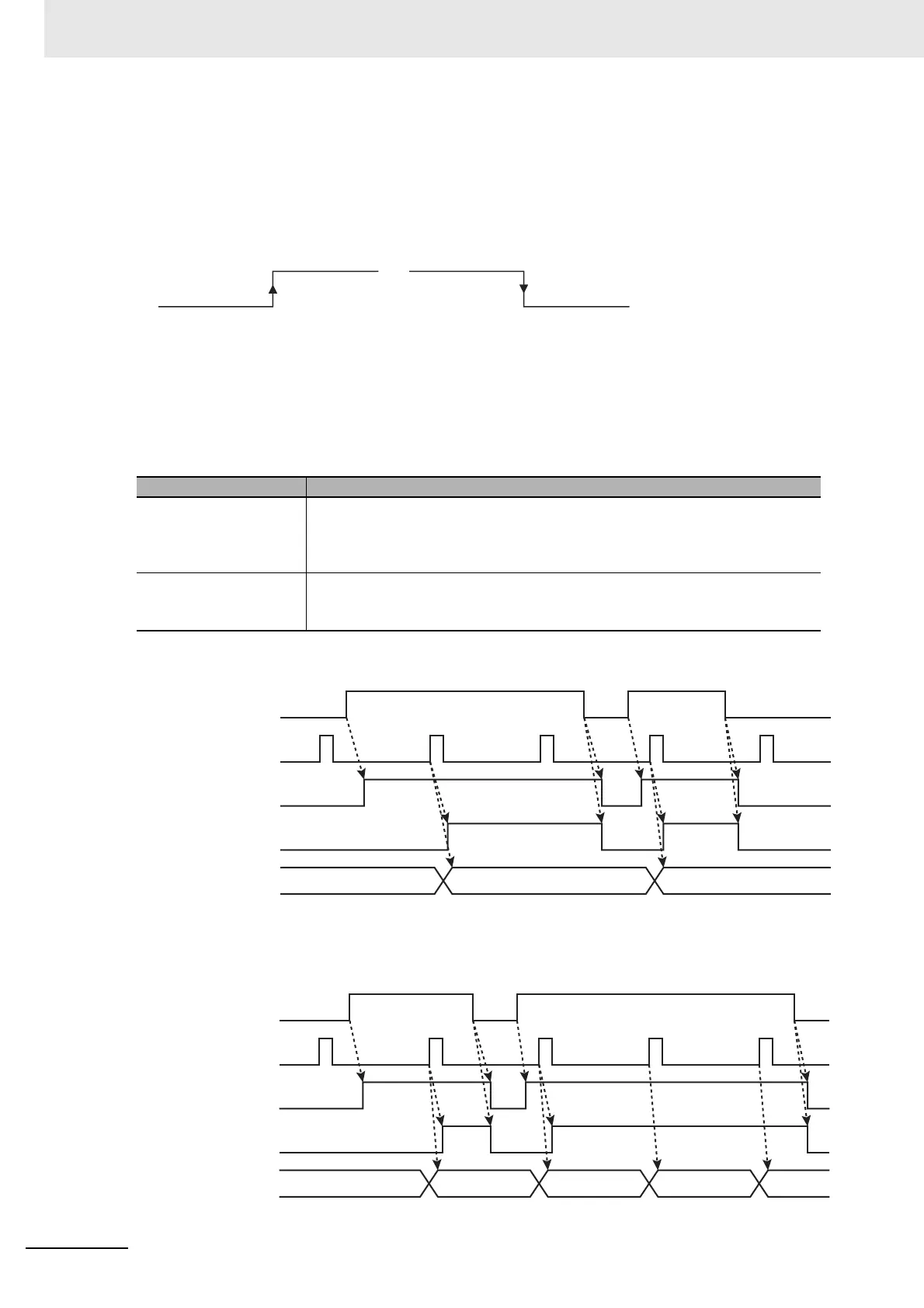
When you set the External Input Logic Selection parameter for the external input (I0, I1, or I2) to specify
an N.O. contact, the counter is latched on the rising edge of the selected external input. When you set
the External Input Logic Selection parameter for the external input to specify an N.C. contact, the coun-
ter is latched on the falling edge of the external input. The latch value is updated every time the counter
value is latched.
You can assign up to two external inputs as latch inputs, each with an I/O data input area allocation.
Trigger Conditions
There are the following two input trigger conditions for latching:
The following timing chart shows the operation in One-shot Mode.
The following timing chart shows the operation in Continuous Mode.
Input trigger condition Description
One-shot Mode After you change Latch Input 1 Enable or Latch Input 2 Enable bit from 0 to 1, the
present position of the encoder is latched for the first detected latch input. No
more latching is performed for this latch input until you change the Latch Input 1
Enable or Latch Input 2 Enable bit to 0 and then back to 1 again.
Continuous Mode While the Latch Input 1 Enable or Latch Input 2 Enable bit is 1, the present posi-
tion of the encoder is latched and the latch value is updated every time a latch
input is detected.
Latch data is updated
to the present value.
Latch data is updated
to the present value.
N.O. contact N.C. contact
Latch Input Enable bit
(software switch)
Trigger input
Latch Input
Completed Flag
Latch data
Latch Input
Enabled bit
(status)
Latch Input Enable bit
(software switch)
Trigger input
Latch Input
Enabled bit
(status)
Latch Input
Completed Flag
Latch data

 Loading...


