7 - 43
7 SSI Input Units
NX-series Position Interface Units User’s Manual (W524)
7-9 Functions
7
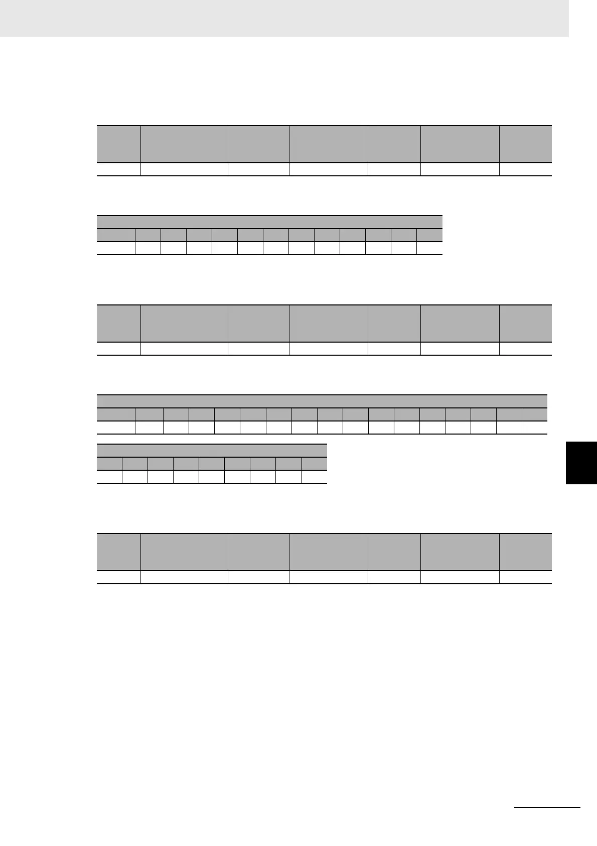
7-9-2 SSI Data Settings
Note 1. M0, M1, etc., are the data bits that give the number of rotations.
2. S0, S1, etc., are the data bits that give the absolute position during a single rotation.
Single-turn 9-bit Data and Alarm Bit
Note 1. S0, S1, etc., are the data bits that give the number of rotations.
2. A is a bit that indicates an error.
Tannen Baum Multi-turn 9-bit and Single-turn 12-bit Data
Note 1. M0, M1, etc., are the data bits that give the number of rotations.
2. S0, S1, etc., are the data bits that give the absolute position during a single rotation.
Valid
data
length
Single-turn data
start bit
Single-turn
data length
Multi-turn data
start bit
Multi-turn
data
length
Status data start
bit
Status
data
length
25 12 13 0 12 0 0
Received frame bit positions
0: MSB 1 2 3 4 5 6 7 8 9 10 11 12
S8 S7 S6 S5 S4 S3 S2 S1 S0 0 0 A 0
Valid
data
length
Single-turn data
start bit
Single-turn
data length
Multi-turn data
start bit
Multi-turn
data
length
Status data start
bit
Status
data
length
13 0 9 0 0 11 1
Received frame bit positions
0: MSB 1 2 3 4 5 6 7 8 9 10 11 12 13 14 15 16
0 0 0 M8M7M6M5M4M3M2M1M0S11S10S9 S8 S7
Received frame bit positions
17 18 19 20 21 22 23 24 25
S6 S5 S4 S3 S2 S1 S0 0 0
Valid
data
length
Single-turn data
start bit
Single-turn
data length
Multi-turn data
start bit
Multi-turn
data
length
Status data start
bit
Status
data
length
26 3 12 12 9 0 0