8 Pulse Output Units
8 - 50
NX-series Position Interface Units User’s Manual (W524)
Precautions for Correct Use
• Be careful of the wiring and settings that are required when you assign a positive drive pro-
hibit input, negative drive prohibit input, immediate stop input, or home proximity input to an
input bit of a Digital Input Unit. Conform that the target signal turns ON and OFF correctly
before you turn ON the power to the motor.
• You can select the input logic for the positive drive prohibit, negative drive prohibit, immediate
stop, and home proximity inputs in the axis parameter settings of the MC Function Module.
For the Pulse Output Unit, leave the positive drive prohibit, negative drive prohibit, and imme-
diate stop inputs at their Sysmac Studio default settings for N.O. contacts.
Consider the operation when the input signal is disconnected for these inputs and set the
input logic accordingly.
• Input signals that use a Digital Input Unit are detected by the MC Function Module.
Emergency stop circuits, interlock circuits, limit circuits, and similar safety measures must be
provided in external control circuits.
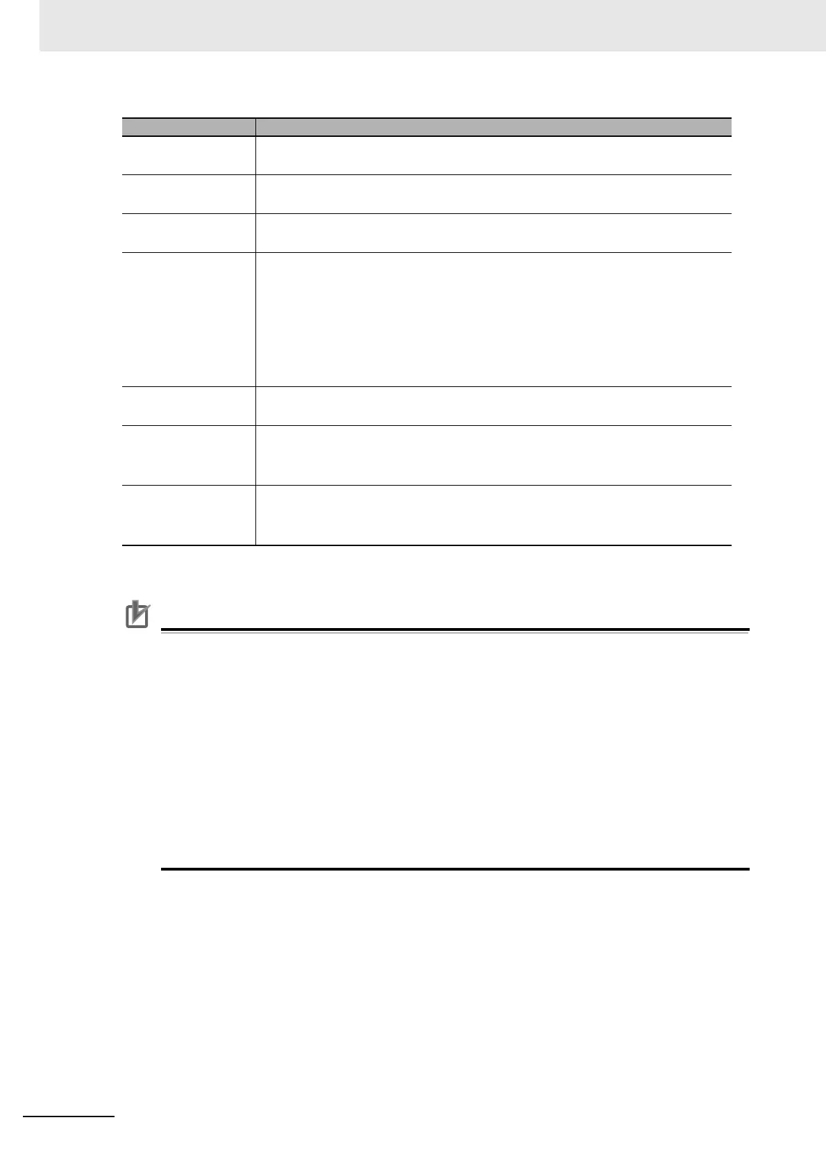
Function Description
Positive drive prohibit
input
This signal is used for the positive limit input.
Set the PDO of the corresponding input bit of the Digital Input Unit.
Negative drive pro-
hibit input
This signal is used for the negative limit input.
Set the PDO of the corresponding input bit of the Digital Input Unit.
Immediate stop input This signal is used for the immediate stop input.
Set the PDO of the corresponding input bit of the Digital Input Unit.
Encoder phase-Z
input
This input gives the detected status of the phase-Z input.
This input is not used with the Pulse Output Unit.
Set it to No assignment.
With a Pulse Output Unit, external latch input 1 is used as the home input signal. Use
an external home sensor or the encoder phase-Z signal for the home input signal.
Connect the home input signal to external input 0 on the Pulse Output Unit and set
the External Input 0 Function Selection parameter to latch input 1.
*1
*1. Refer to 8-10-6 External Input Function Selection on page 8-65 for details and to 9-3 Setting Examples on
page 9-7 for setting examples.
Home proximity input This signal is used for the home proximity input.
Set the PDO of the corresponding input bit of the Digital Input Unit.
External latch input 1 This input gives the status of the signal that is used for external latch input 1.
Set it to the latch 1 input of the Pulse Output Unit.
This is the default Sysmac Studio setting.
External latch input 2 This input gives the status of the signal that is used for external latch input 2.
Set it to the latch 2 input of the Pulse Output Unit.
This is the default Sysmac Studio setting.

 Loading...


