9 Application Example
9 - 10
NX-series Position Interface Units User’s Manual (W524)
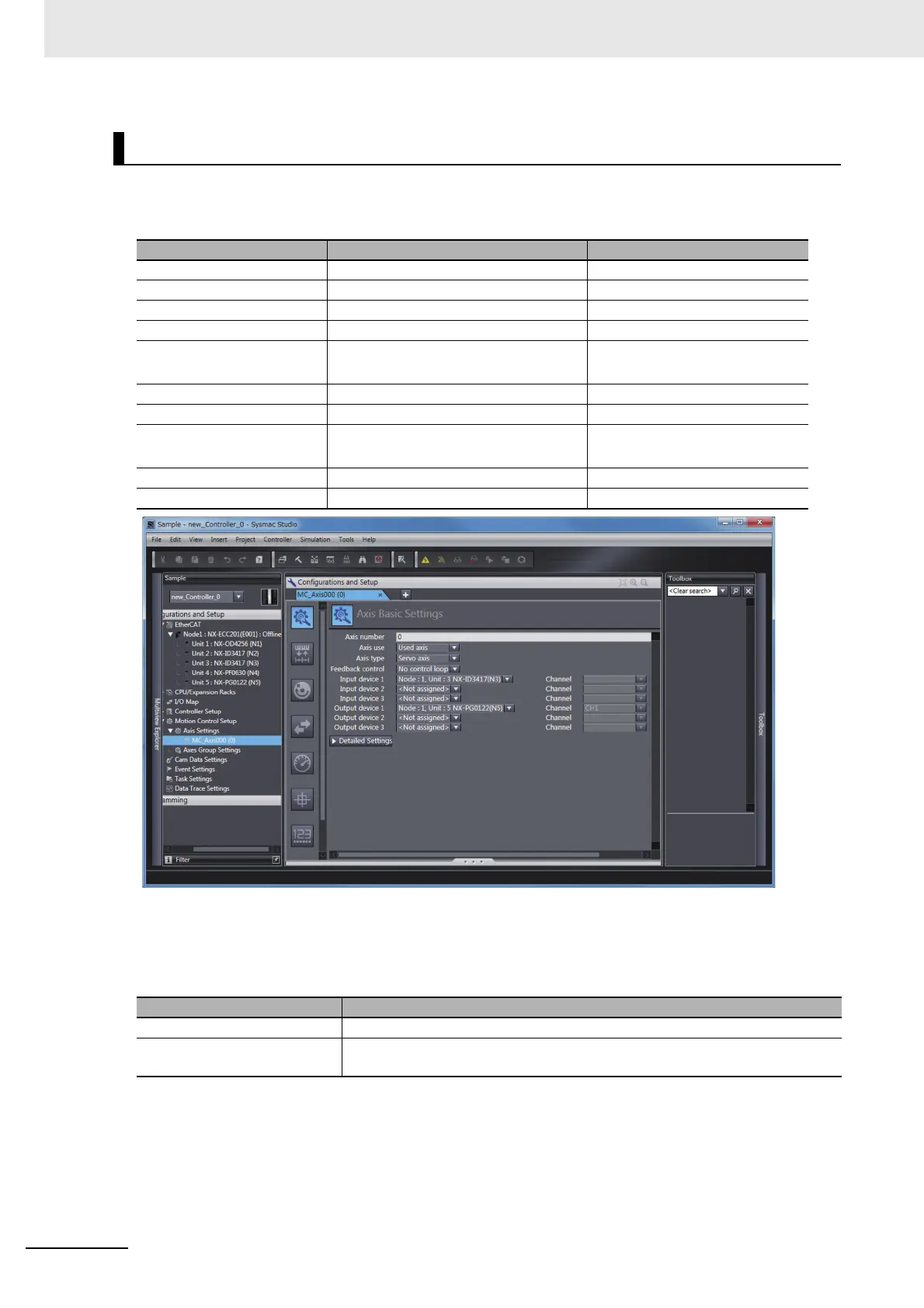
For this example we will assign the Pulse Output Unit and Digital Input Units to axis 1.
Perform the following settings on the Axis Basic Settings Display in the Sysmac Studio.
The following default I/O entry mappings are set as the process data assignments for the Pulse Output
Unit and the process data is automatically assigned to the appropriate axis functions.
Leave these settings on their default settings to use the MC Function Module.
Axis Assignments and Settings
Parameter Setting Remarks
Axis Number 0 Assigns axis 0.
Axis Use Used Axis
Axis Type Servo axis
Feedback Control No control loop
Input Device 1 NX Unit No. 3:
NX-ID3417 Digital Input Unit
Select the Digital Input Unit to
assign to the axis.
Input Device 2 ---
Input Device 3 ---
Output Device 1 NX Unit No. 5:
NX-PG0122 Pulse Output Unit
Select the Pulse Output Unit.
Output Device 2 ---
Output Device 3 ---
I/O entry mapping Function
Inputs (RxPDO) Controlword, Command Position, Command Velocity, and Latch Input
Outputs (TxPDO) Statusword, External Input Status, Command Current Position, Latch Status,
Latch Input 1 Data, and Latch Input 2 Data
 Loading...


