Appendices
A - 12
NX-series Position Interface Units User’s Manual (W524)
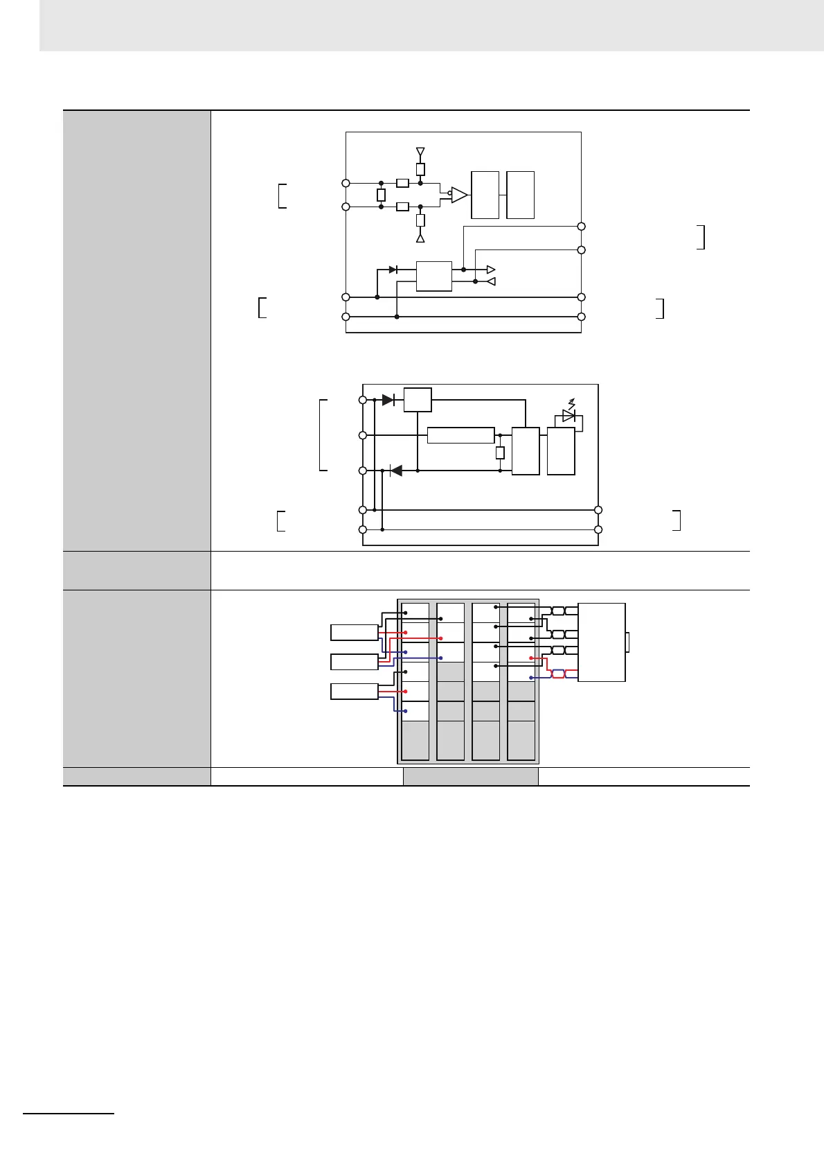
Circuit layout
Encoder Input
External Inputs
Installation orientation
and restrictions
Installation orientation: 6 possible orientations
Restrictions: There are no restrictions.
Terminal connection
diagram
Failure detection None Protection None
*1. The I/O refreshing method is automatically set according to the connected Communications Coupler Unit and CPU Unit.
No isolation: 5 V GND
No isolation: 5 V
No isolation: 5 V GND
Encoder power supply output, 5 V
Encoder power supply output, 0 V
Terminal
block
Non-
isolated
power
supply
Inter-
nal
cir-
cuits
120
Ω
A-, B-, Z-
A+, B+, Z+
Terminal
block
Isola-
tion
cir-
cuit
No isolation: 5 V
I/O power supply +
I/O power supply
−
I/O power supply +
I/O power supply
−
Left-side
NX bus
connector
Right-side
NX bus
connector
A, B, Z
I0 to I2
Inter-
nal
cir-
cuits
IOG
IOV
I/O power supply +
I/O power supply
−
I/O power supply +
I/O power supply
−
Terminal block
Left-side
NX bus
connector
Right-side
NX bus
connector
Isola-
tion
cir-
cuit
Current limiter
Power
supply
I0
IOV
IOG
I1 A+
A-
Z+
Z-
B+
B-
5V
0V
IOV
IOG
I2
IOV
IOG
NC
NC
NC
NC
NC
NC
NC
Sensor 1
Sensor 2
Sensor 3
Encoder

 Loading...


