Appendices
A - 42
NX-series Position Interface Units User’s Manual (W524)
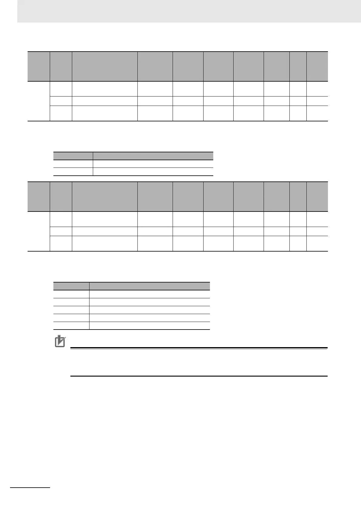
• The following table shows the logic settings for the External Input 1 object.
• The following table shows the settings for the External Input 2 object.
Precautions for Correct Use
Except for the general input setting, you cannot set more than one of the external inputs 0
through 2 to the same setting. If the same setting is used for more than one external input, all
external inputs 0 through 2 are disabled and an External Input Setting Error event will occur.
Index
(hex)
Subin-
dex
(hex)
Object name Default
Data
range
Unit Data type Access
I/O
allo-
cat-
ion
Data
attri-
bute
5015 --- External Input 1 Logic
Selection
--- --- --- --- --- --- ---
00 Number of Entries
1
*1
*1. Setting is not possible for the NX-EC0212 and NX-EC0222.
1 *1 --- USINT RO No ---
01 Ch1 External Input 1
Logic Selection
0 0 or 1 --- USINT RW No Y
Set value Description
0 N.O. (Normally open)
1 N.C. (Normally close)
Index
(hex)
Subin-
dex
(hex)
Object name Default
Data
range
Unit Data type Access
I/O
allo-
cat-
ion
Data
attri-
bute
5016 --- External Input 2 Function
Selection
--- --- --- --- --- --- ---
00 Number of Entries
1
*1
*1. Setting is not possible for the NX-EC0212 and NX-EC0222.
1 *1 --- USINT RO No ---
01 Ch1 External Input 2
Function Selection
0 0 to 4 --- USINT RW No Y
Set value Description
0 General input (factory default)
1 Latch input 1
2 Latch input 2
3 Gate input
4 Reset input

 Loading...


