Appendices
A - 52
NX-series Position Interface Units User’s Manual (W524)
• Set this object to the resolution for single-turn data.
• If this object is set to 0, the resolution is the maximum setting value for single-turn data + 1.
• If the resolution is greater than the range represented by the value set for the Single-turn Data Length
object, SSI communications are disabled and an SSI Data Setting Error event occurs.
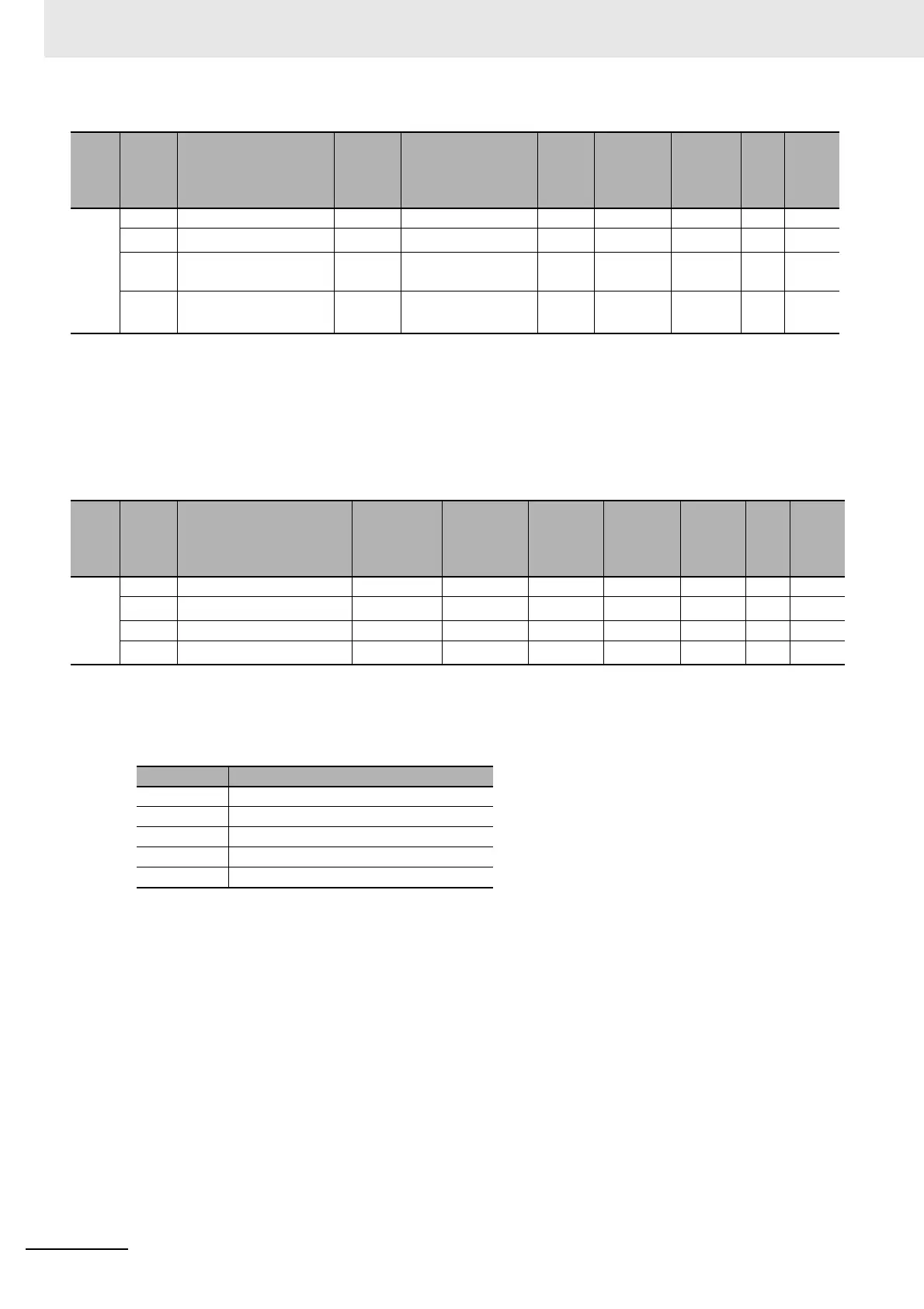
• The following table shows the settings for the Coding Method Setting object.
Index
(hex)
Subin-
dex
(hex)
Object name Default Data range Unit Data type Access
I/O
allo-
cat-
ion
Data
attri-
bute
500E --- Encoder Resolution --- --- --- --- --- --- ---
00 Number of Entries
*1
*1. The values for the NX-ECS112 are 1. The values for the NX-ECS212 are 2.
*1 --- USINT RO No ---
01 Ch1 Encoder Resolu-
tion
0 0 to 4,294,967,295 --- UDINT RW No Y
02 Ch2 Encoder Resolu-
tion
*2
*2. This object does not exist on the NX-ECS112.
0 0 to 4,294,967,295 --- UDINT RW No Y
Index
(hex)
Subin-
dex
(hex)
Object name Default Data range Unit Data type Access
I/O
allo-
cat-
ion
Data
attri-
bute
500F --- Coding Method --- --- --- --- --- --- ---
00 Number of Entries
*1
*1. The values for the NX-ECS112 are 1. The values for the NX-ECS212 are 2.
*1 --- USINT RO No ---
01 Ch1 Coding Method 3 0 to 4 --- USINT RW No Y
02
Ch2 Coding Method
*2
*2. This object does not exist on the NX-ECS112.
3 0 to 4 --- USINT RW No Y
Set value Description
0 No change
1 Output binary codes.
2 Change gray codes to binary codes.
3 Change binary codes to present values.
4 Change gray codes to present values.
 Loading...


