4 - 33
4 Installation and Wiring
NX-series Digital I/O Unit User’s Manual (W521)
4-3 Wiring the Terminals
4
4-3-2 Wiring to Connectors
Available Connectors
Use the following connectors when assembling a connector and cable.
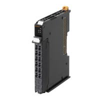
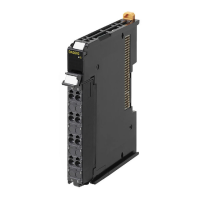
NX Units with MIL Connectors
Applicable Cable-side Connectors
Wire Size
We recommend using cable with wire gauges of AWG 24 or AWG 28 (0.2 mm
2
to 0.08 mm
2
). Use
cable with external wire diameters of 1.61 mm max.
Wiring
• Make sure that all Units are connected properly.
• After the cable side connector is connected, close the lock lever on the NX Unit side connector
section to lock it. After you complete the wiring, make sure that the connector is locked.
If the external power supply has polarity, connect it with the correct polarity. If the polarity is
reversed, current may flow in the reverse direction and damage the connected devices regard-
less of the operation of the Controller.
Using User-made Cables with Connector
Model Specifications Pins
NX-ID5142-5 DC Input Unit, 16 points 20
NX-ID6142-5 DC Input Unit, 32 points 40
NX-OD5121-5 Transistor Output Unit, 16 points 20
NX-OD5256-5
NX-OD6121-5 Transistor Output Unit, 32 points 40
NX-OD6256-5
NX-MD6121-5 DC Input/Transistor Output Units, 16 inputs, 16
outputs
20 (x 2)
NX-MD6256-5
Connection Pins OMRON set DDK parts
Pressure-welded 40 XG4M-4030-T FRC5-A040-3TOS
20 XG4M-2030-T FRC5-A020-3TOS

 Loading...


