3 Part Names and Functions
3 - 2
NX-series Digital I/O Unit User’s Manual (W521)
3-1 Part Names
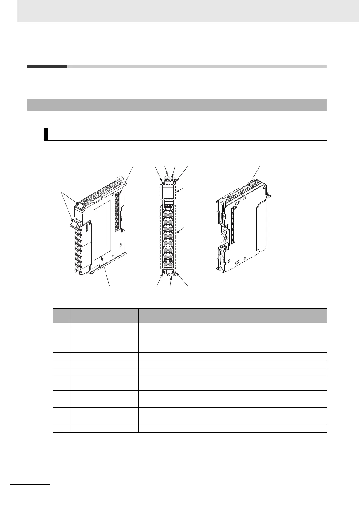
This section describes the names and functions of the Digital I/O Unit parts.
3-1-1 Screwless Clamping Terminal Block Type
NX Units (12 mm Width)
Let-
ter
Name Function
(A) Marker attachment loca-
tions
The locations where markers are attached. The markers made by OMRON
are installed for the factory setting. Commercially available markers can also
be installed.
Refer to 4-1-2 Attaching Markers on page 4-4
(B) NX bus connector This connector is used to connect each Unit.
(C) Unit hookup guides These guides are used to connect two Units.
(D) DIN Track mounting hooks These hooks are used to mount the NX Unit to a DIN Track.
(E) Protrusions for removing
the Unit
The protrusions to hold when removing the Unit.
(F) Indicators The indicators show the current operating status of the Unit.
Refer to 3-2 Indicators on page 3-9
(G) Terminal block The terminal block is used to connect external devices.
The number of terminals depends on the type of Unit.
(H) Unit specifications The specifications of the Unit are given.
(C)(D)
(H)
(G)
(F)
(C)
(A)
(E)
(C)(E)
(C)
(B)
(B)
 Loading...