4 - 45
4 Installation and Wiring
NX-series Digital I/O Unit User’s Manual (W521)
4-4 Wiring Examples
4
4-4-1 Wiring the Input Units
(d) Precautions on sensor inrush current
An incorrect input may occur due to sensor inrush current if a sensor is turned ON after the DC Input
Unit has started up to the point where inputs are possible.
Determine the time required for sensor operation to stabilize after the sensor is turned ON and take
appropriate measures, such as inserting an ON delay into the user program after turning ON the
sensor.
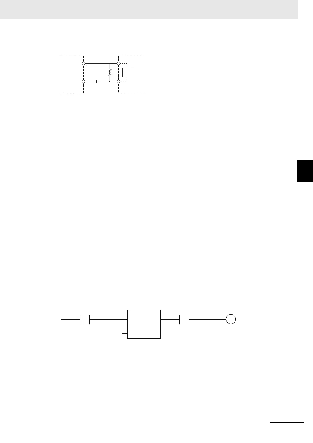
A programming example is shown below.
The sensor's power supply voltage is used as the input bit to Sensor_power.
A 100-ms timer delay (the time required for an OMRON Proximity Sensor to stabilize) is created in
the user program.
After the timer changes to TRUE, input bit X causes the output Output to change to TRUE after the
input of the sensor changes to TRUE.
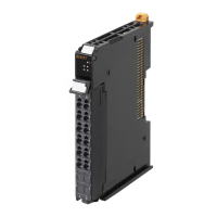
V
CC
: Power supply voltage V
R
: Sensor's output residual voltage
V
ON
: ON voltage of DC Input Unit I
OUT
: Sensor control output (load current)
V
OFF
: OFF voltage of DC Input Unit I
leak
: Sensor leakage current
I
ON
: ON current of DC Input Unit R: Bleeder resistor
I
OFF
: OFF current of DC Input Unit
R
IN
: Input resistor of DC Input Unit
DC Input Unit
RV
R
V
CC
Two-wire sensor
R
IN
TON
T#100ms
X Output
Sensor_power
 Loading...